Fluid control valve

a technology of control valves and valve bodies, applied in the direction of fluid pressure control, process and machine control, instruments, etc., can solve the problems of inability to provide the required instant on-off action, slow rotary motion, and reduced selection of suitable on-off valves, etc., to achieve simple construction, reduce the effect of moving parts and few parts

Inactive Publication Date: 2007-06-05
KERSHAW CHARLES H
View PDF15 Cites 78 Cited by
  • Summary
  • Abstract
  • Description
  • Claims
  • Application Information

AI Technical Summary

Benefits of technology

[0014]It is therefore an object of the present invention to provide a fluid control valve that is relatively simple in construction, having few parts and particularly few moving parts.

Problems solved by technology

As the working fluid pressure increases, the selection of suitable on-off valves decreases due to the difficulties in achieving fluid sealing and in operating the moving valve parts.
In many applications, such rotary motion is too slow and does not provide the required instant on-off action.

Method used


Image

  • Fluid control valve
  • Fluid control valve
  • Fluid control valve

Examples


Embodiment Construction

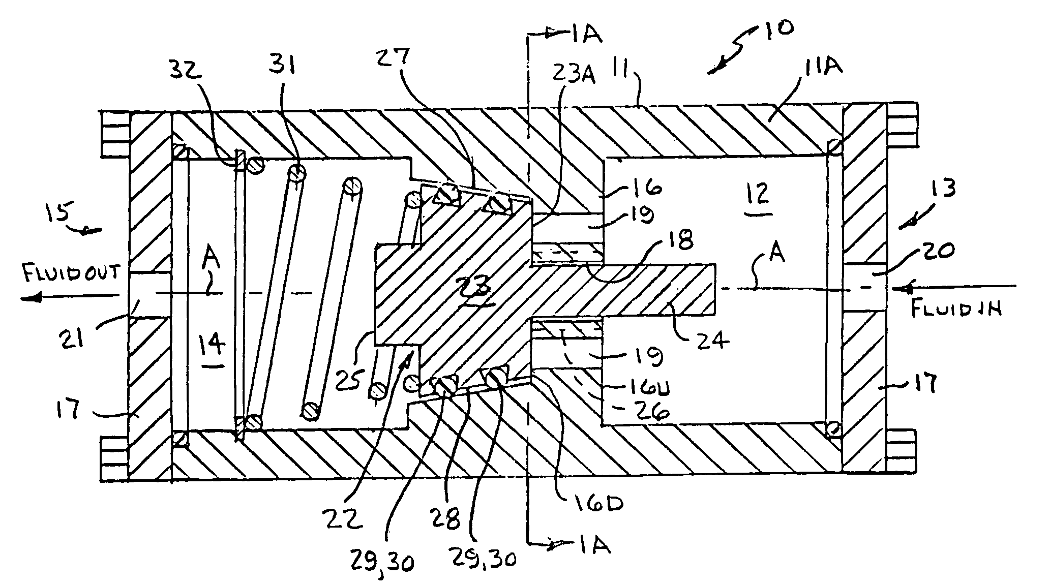
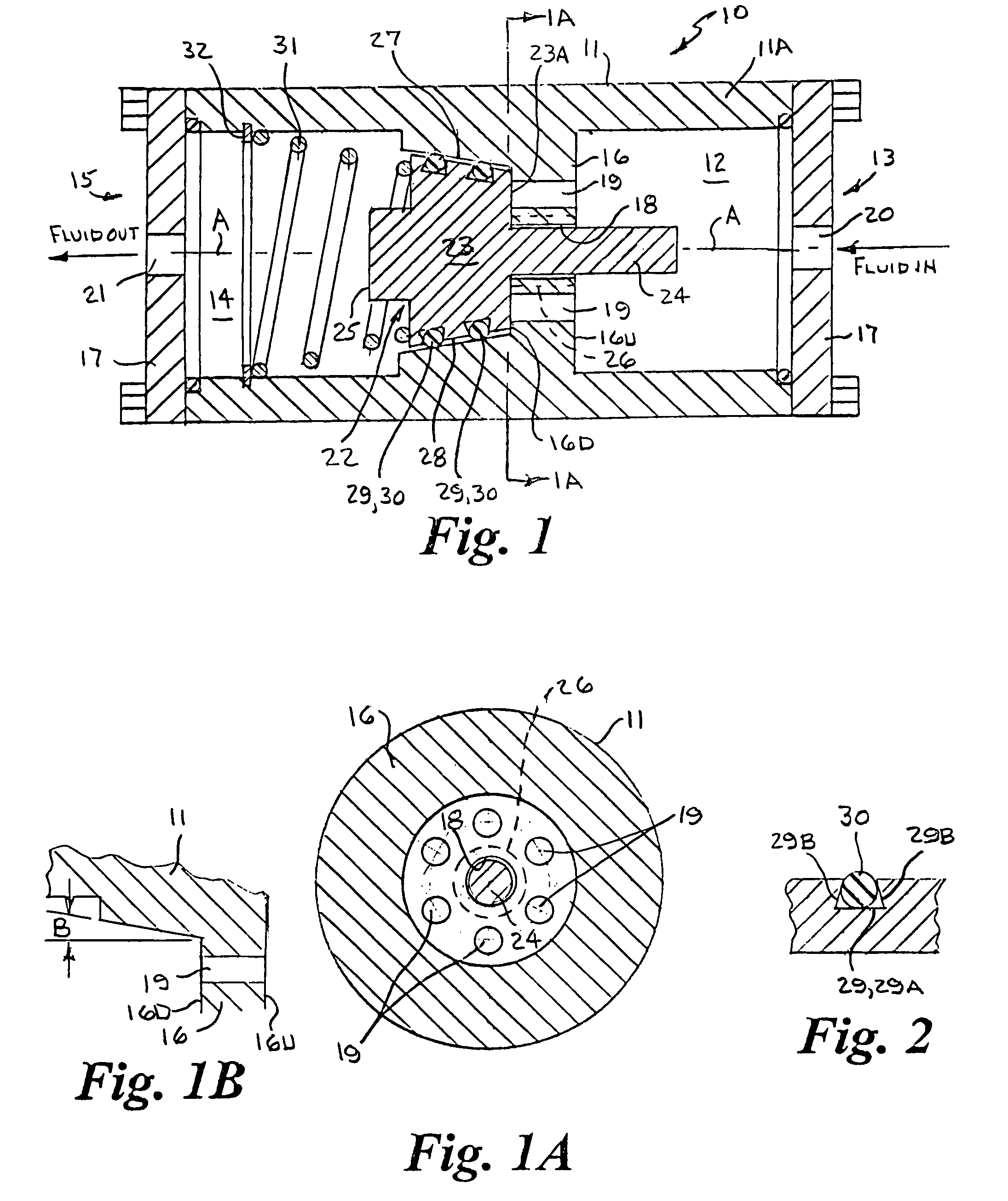
[0030]Referring to FIGS. 1, 1A and 1B of the drawings by numerals of reference, there is shown a preferred normally closed embodiment of the fluid control valve 10. The fluid control valve 10 includes a valve body 11 having a longitudinal axis A, a generally cylindrical upstream chamber 12 extending inwardly from an upstream end 13 and a generally cylindrical downstream chamber 14 extending inwardly from a downstream end 15. For purposes of illustration, the upstream end 13 is shown on the right-hand side of the valve body 11, and downstream end 15 is shown on the left-hand side. The body 11 has an interior wall 16 with an upstream side 16U and a downstream side 16D disposed perpendicular to the longitudinal axis A. The upstream chamber 12 terminates at the upstream side 16U of the interior wall 16, and the downstream chamber 14 terminates at the downstream side 16D. The upstream end of the upstream chamber 12 and the downstream end of the downstream chamber 14 are each sealingly en...


PUM


Abstract

A fluid control valve having a spring biased shuttle plunger member which opens or closes fluid flow through a plurality of radially spaced apart fluid passageways disposed between an upstream chamber and downstream chamber in the valve body responsive to a fluid pressure greater than the spring force and any differential pressure between the upstream and downstream chambers to prevent fluid from being supplied at a pressure higher than a desired operating pressure and prevent high dynamic differential pressures, such as a “water hammer” or explosive pressure. Alternatively, in a normally closed embodiment, pilot fluid at a pressure greater than the spring force and any differential pressure in the upstream chamber is utilized to open the valve, which is then closed by the spring force.

Description

BACKGROUND OF THE INVENTION[0001]1. Field of the Invention[0002]This invention relates generally to fluid control valves, and more particularly to a fluid control valve having a spring biased shuttle plunger member which opens or closes fluid flow between an upstream and downstream side of the valve body responsive to a fluid pressure greater than the spring force and any differential pressure between the upstream and downstream side to prevent fluid from being supplied at a pressure higher than a desired operating pressure and prevent high dynamic differential pressures, such as a “water hammer” or explosive pressure.[0003]2. Background Art[0004]Fluid control valves of the on-off type that allow full fluid flow or completely shut off the fluid flow are well known in the art and are available in a wide range of various designs, sizes, pressure capabilities, and modes of operation. Such conventional valves are often identified by the configuration of the main valve components, such a...

Claims


Application Information

Patent Timeline
Patent Type & Authority Patents(United States)
IPC IPC(8): F16K17/04
CPCF16K17/06F16K17/30F16K17/34F16K31/1225G05D16/107G05D16/187Y10T137/7839Y10T137/7866Y10T137/7939
Inventor KERSHAW, CHARLES H.
Owner KERSHAW CHARLES H
Why Eureka
Try Eureka