Device for Changing the Direction of Travel of a Rail-Bound Vehicle, Rail-Bound Ride Having Such a Device, and Method for Operating Such a Device

Active Publication Date: 2016-10-06
MACK RIDES
View PDF0 Cites 5 Cited by
  • Summary
  • Abstract
  • Description
  • Claims
  • Application Information

AI Technical Summary

Benefits of technology

The patent describes a device for changing the direction of motion of a rail-bound vehicle. The device has a connecting rail section that can move in two directions: a first direction when the vehicle is riding on the feeding rail section and a second direction when the vehicle is riding on the removing rail section. The connecting rail section can also perform a wobbling motion. The device can be controlled to move the connecting rail section at least once during its motion. The device can be installed on a guide rail that describes a closed curve or a constant distance between the sections of the guide rail. The device can be used on a rail-bound ride, such as a rollercoaster, to change its direction of travel. The technical effects of the device include improved control over the vehicle's motion and a more immersive experience for the ride's occupants.

Problems solved by technology

In addition to steep declines and drop sections, tight curves generating the feeling that the vehicle is thrown off the track, and effects suggesting a seemingly unavoidable collision are here particularly also sudden and unexpected changes of the direction of motion, and thus a plurality of devices have been developed to change the direction of motion of a rail-bound vehicle.

Method used


Image

  • Device for Changing the Direction of Travel of a Rail-Bound Vehicle, Rail-Bound Ride Having Such a Device, and Method for Operating Such a Device
  • Device for Changing the Direction of Travel of a Rail-Bound Vehicle, Rail-Bound Ride Having Such a Device, and Method for Operating Such a Device
  • Device for Changing the Direction of Travel of a Rail-Bound Vehicle, Rail-Bound Ride Having Such a Device, and Method for Operating Such a Device

Examples


Embodiment Construction

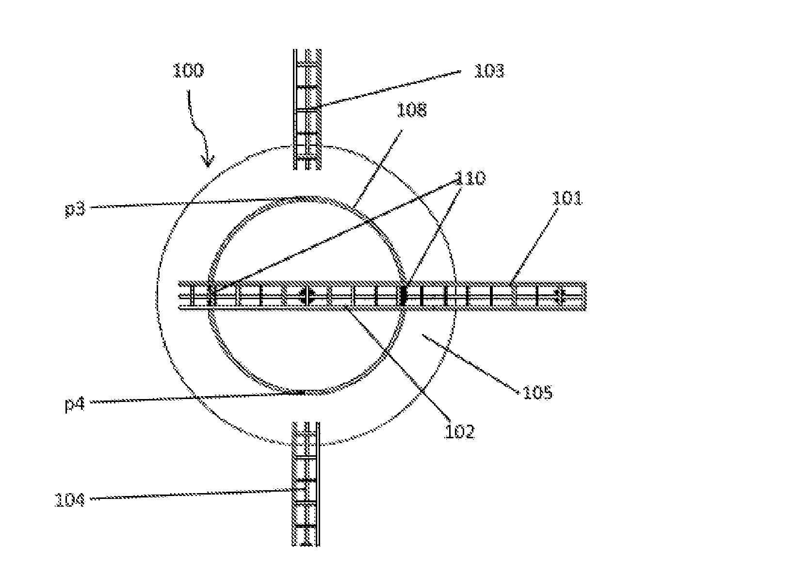
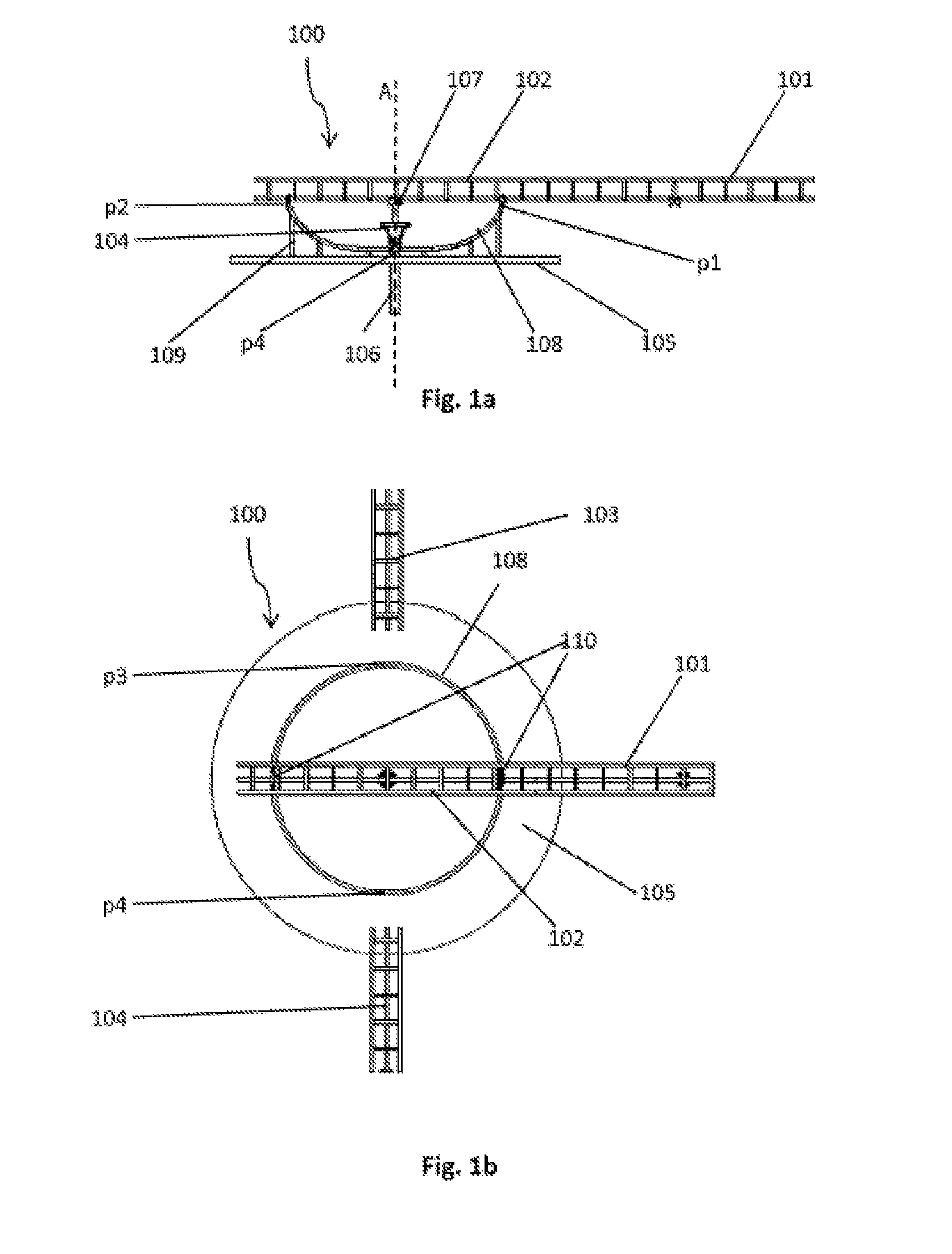
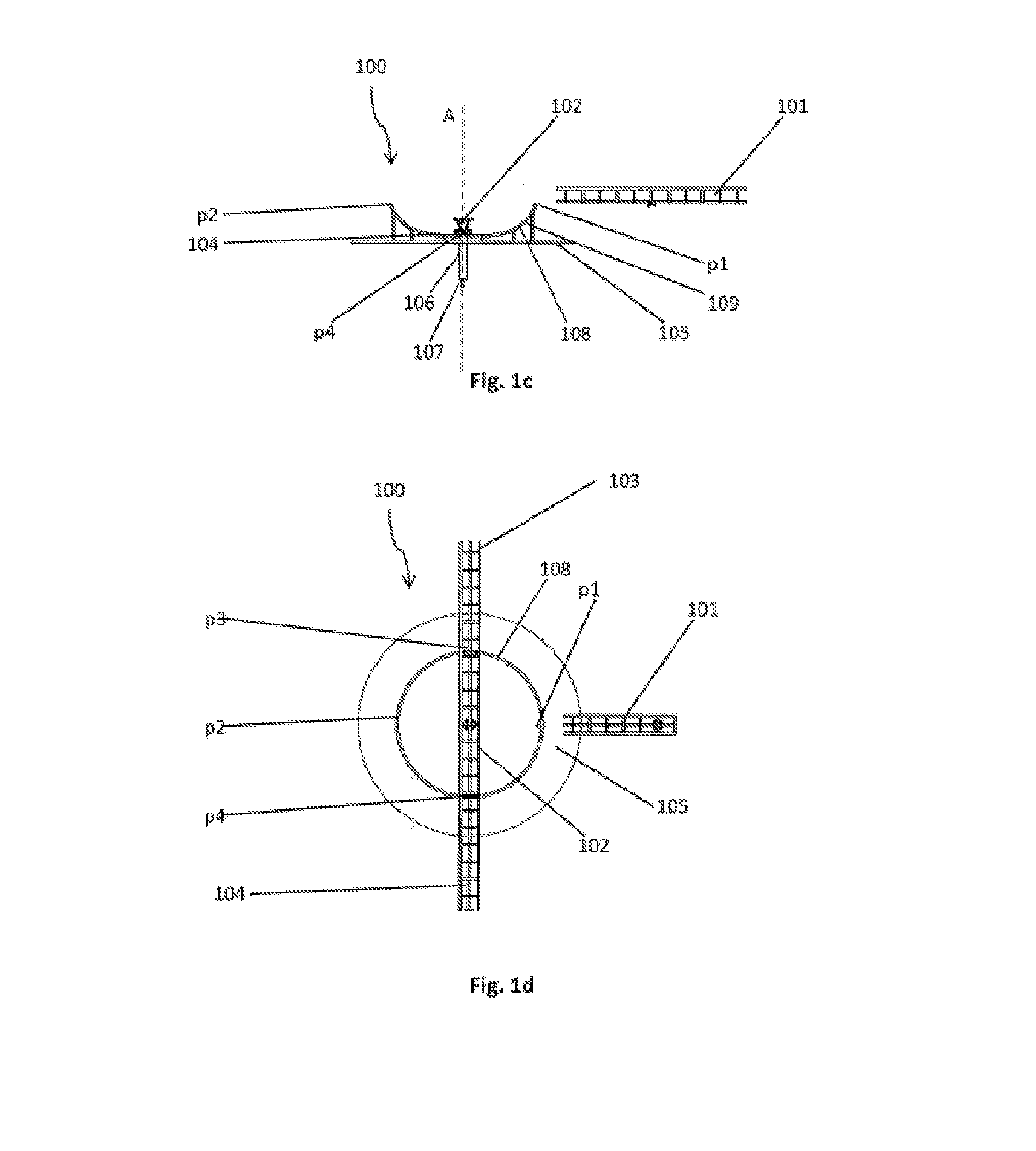
[0039]The device according to the invention for changing the direction of motion of a rail-bound vehicle comprises (at least) one feeding rail section, (at least) one removing rail section, and a connecting rail section, which by a motion, representing at least a rotary motion about an axis of rotation, i.e. a rotation about the axis of rotation by an angle of rotation amounting particularly less than 360°, can move the rail out of a first position in which the connecting rail section is arranged in reference to the feeding rail section such that the rail-bound vehicle can ride onto the connecting rail section into a second position, in which the connecting rail section is arranged in reference to the removing rail section such that the vehicle can run onto the removing rail section. Here the term “direction of rotation” in the sense of the invention includes both rotary motions about an axis in which the distance from said axis remains constant as well as those in which the distanc...


PUM


Abstract

The invention relates to a device for changing the direction of travel of a rail-bound vehicle, comprising a feeding rail section, a removing rail section, and a connecting rail section, which can be moved from a first position, in which the connecting rail section is arranged in relation to the feeding rail section in such a way that the rail-bound vehicle can drive onto the connecting rail section, to a second position, in which the connecting rail section is arranged in relation to the removing rail section in such a way that the vehicle can drive onto the removing rail section, by means of a motion comprising at least one rotational motion about an axis of the rotational motion. The invention further relates to a rail-bound ride having such a device, and to a method for operating such a device.

Description

CROSS REFERENCE TO RELATED APPLICATIONS[0001]This patent application claims priority International Patent Application PCT / EP2014 / 071326, filed on Oct. 6, 2014, and thereby to German Patent Application 10 2014 101 007.8, filed on Jan. 28, 2014.STATEMENT REGARDING FEDERALLY SPONSORED RESEARCH OR DEVELOPMENT[0002]No federal government funds were used in researching or developing this invention.NAMES OF PARTIES TO A JOINT RESEARCH AGREEMENT[0003]Not applicable.SEQUENCE LISTING INCLUDED AND INCORPORATED BY REFERENCE HEREIN[0004]Not applicable.BACKGROUND[0005]1. Field of the Invention[0006]The present invention relates to a device for changing direction of travel of a rail-bound vehicle, a rail-bound ride comprising such a device and a method of operating such a device.[0007]2. Background of the Invention[0008]Rail-bound rides, particularly roller coasters, are some of the most favored attractions of amusement parks, folk festivals, and fairs. Particularly positive effects upon the amusem...

Claims


Application Information

Patent Timeline
IPC IPC(8): B61J1/08A63G7/00A63G21/04B61J1/02
CPCB61J1/08A63G21/04A63G7/00B61J1/02A63G21/14
Inventor SORNIK, FRANKGORDT, DENNIS
Owner MACK RIDES
Why Eureka
Try Eureka