Pressure sensitive sensor and touch panel

a technology of pressure which is applied in the field of pressure sensitive sensor and touch panel, can solve the problems of difficult detection of accurate pressing force and and achieve the effect of suppressing the drop in the accuracy of detecting pressing for

Inactive Publication Date: 2016-11-24
NISSHA PRINTING COMPANY
View PDF3 Cites 26 Cited by
  • Summary
  • Abstract
  • Description
  • Claims
  • Application Information

AI Technical Summary

Benefits of technology

[0012]According to this configuration, a position of a user's finger or the like that makes contact with or approaches the operation surface of the panel member (called a “touch position”) can be determined in the same manner as with a conventional electrostatic capacitance-type touch panel. In other words, the touch position on the operation surface in an X-Y coordinate system can be appropriately determined on the basis of a change in the respective self capacitances of the first electrodes and the second electrodes or a change in the mutual capacitance between the first electrodes and the second electrodes. In addition, when the operation surface of the panel member is touched by a user's finger or the like, the panel member elastically deforms, which in turn deforms the variable resistance electrode. The electrical resistance of the deformed variable resistance electrode changes in response to that deformation (change in posture). This enables the magnitude of a pressing force on the covering member to be determined by detecting the amount of the change in the electrical resistance.
[0013]At this time, the electrical resistance of the variable resistance electrode can change in response to a change in the ambient temperature, but the pyroelectric material layer disposed covering the variable resistance electrode self-polarizes and produces a charge in response to a change in the ambient temperature. By detecting that produced charge using the pair of charge detection electrodes on both sides of the pyroelectric material layer, a change in the electrical resistance of the variable resistance electrode based on a change in the ambient temperature can be compensated for using the detection result. Accordingly, it is possible to detect only the amount of a change in the electrical resistance caused by the deformation of the variable resistance electrode, regardless of a change in the ambient temperature, and as a result, a drop in the accuracy of detecting the pressing force can be suppressed even in the case where the ambient temperature changes.

Problems solved by technology

There are thus cases where the effects of ambient temperature cause a drop in the accuracy of detecting the pressing force.
As a result, it has been difficult to detect an accurate pressing force.

Method used


Image

  • Pressure sensitive sensor and touch panel
  • Pressure sensitive sensor and touch panel
  • Pressure sensitive sensor and touch panel

Examples


Embodiment Construction

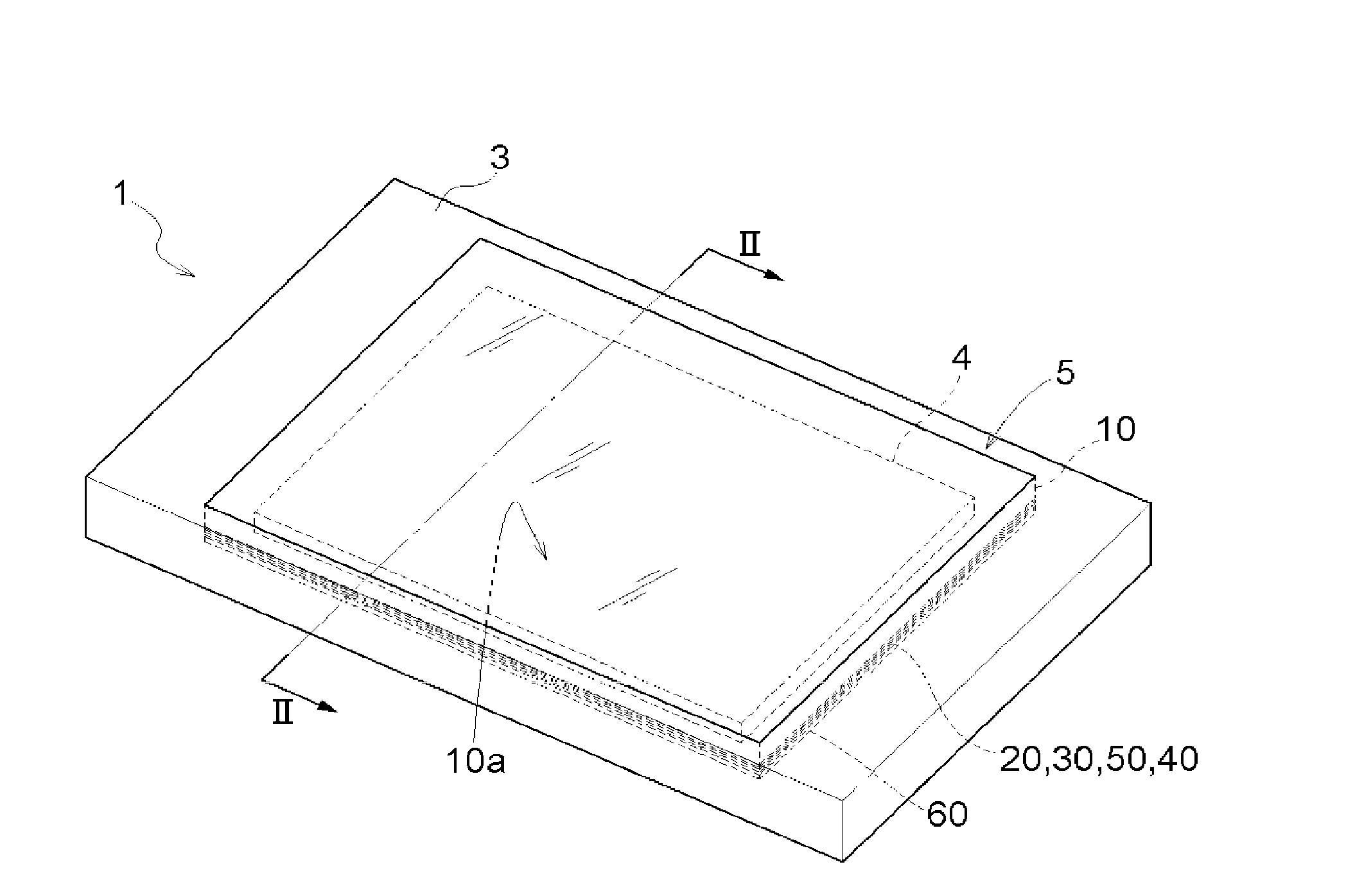
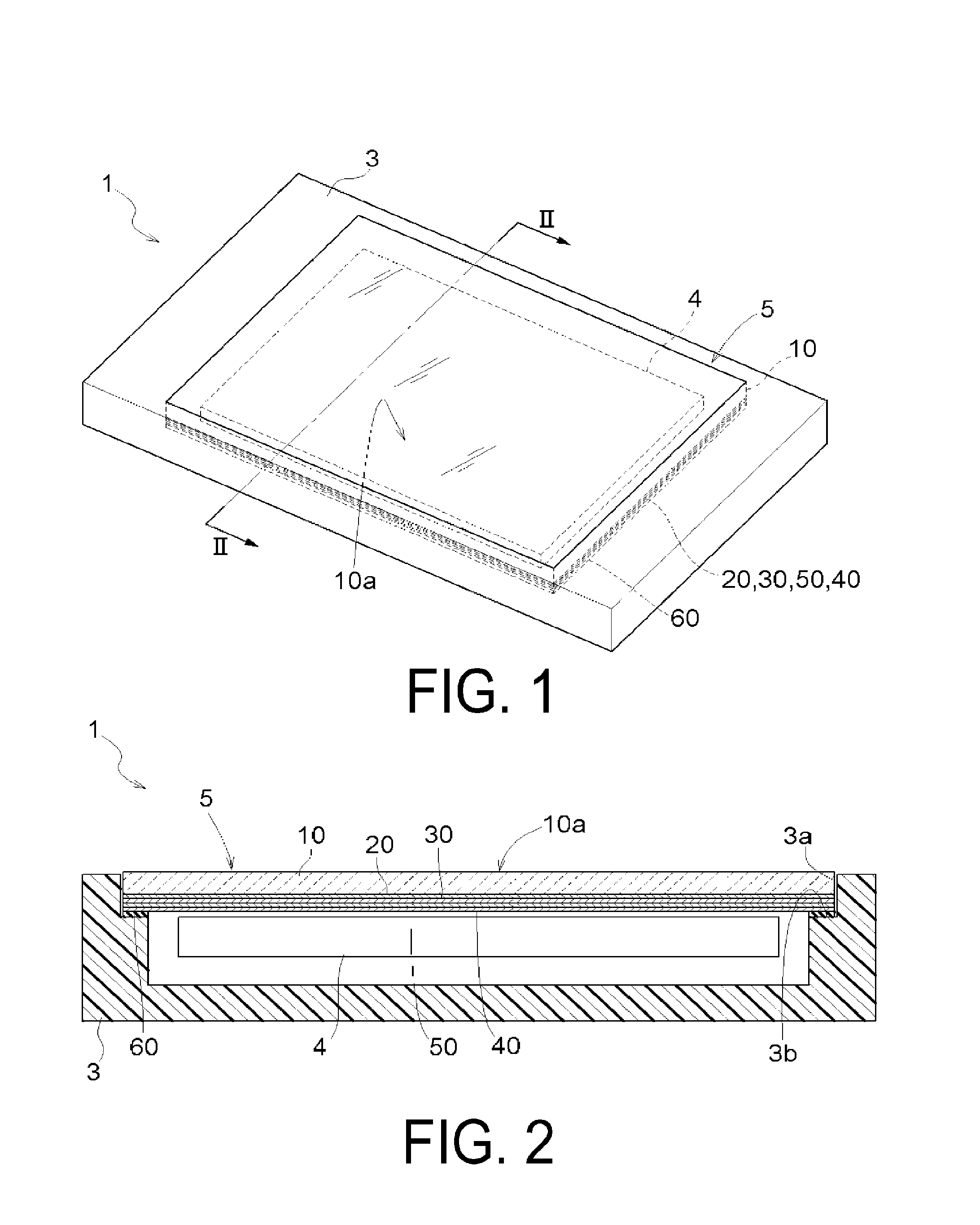
[0033]A touch panel according to the present invention will be described with reference to the drawings. A touch panel 5 according to the present embodiment is provided in an electronic device 1 such as a cellular phone or a mobile gaming device, and functions as a touch input device. For the present embodiment, a description will be given of an example in which the touch panel 5 is provided in a multifunction cellular phone (a smartphone) serving as a type of the electronic device 1. Note that a side on which an input surface (an operation surface 10a, which will be described later) of the touch panel 5 serving as the touch input device is located will be called “front surface side” in the following descriptions. This “front surface side” is a side that faces a user who is operating the electronic device 1. Conversely, a back side as viewed from the user who is operating the electronic device 1 will be called a “rear surface side”.

[0034]As illustrated in FIGS. 1 and 2, the electron...


PUM

PropertyMeasurementUnit
electrical resistanceaaaaaaaaaa
pressing forceaaaaaaaaaa
self capacitanceaaaaaaaaaa

Abstract

Problem: To achieve a pressure sensitive sensor capable of suppressing a drop in the accuracy of detecting a pressing force even in cases where the ambient temperature changes.
Resolution means: A pressure sensitive sensor (7) includes: an elastically deformable covering member (10A) covering a front surface side; a variable resistance electrode (42A), electrical resistance thereof changing in response to a change in posture; a pyroelectric material layer (50) disposed covering the variable resistance electrode (42A); and a pair of charge detection electrodes (51, 52) disposed on both sides of the pyroelectric material layer (50) in a layering direction (L).

Description

TECHNICAL FIELD[0001]The present invention relates to a pressure sensitive sensor that detects a pressing force and a touch panel having a function for detecting a pressing force (a pressure sensitive touch panel).BACKGROUND ART[0002]A device disclosed in Japanese Unexamined Patent Application Publication No. H05-61592A (Patent Document 1) is known as an example of the above-described pressure sensitive sensor and touch panel. In the device disclosed in Patent Document 1, a flexible touch panel 2 is disposed on a planar pressure sensitive sensor 1 to be in contact with the planar pressure sensitive sensor 1 (see FIG. 1 in Patent Document 1). A sensor including a pressure sensitive sheet 1a constituted of a pressure sensitive resistive sheet or the like is given as an example of the pressure sensitive sensor 1, where a pressing force is detected by detecting a change in a resistance value arising when the pressure sensitive sheet 1a is pressed (see paragraph 0015).[0003]However, the ...

Claims


Application Information

Patent Timeline
Patent Type & Authority Applications(United States)
IPC IPC(8): G06F3/041G01L1/14G06F3/044
CPCG06F3/0414G01L1/146G06F3/044G06F3/0445G06F3/0446G06F2203/04105
Inventor WATAZU, YUJIIMAE, NAOTOOZAKI, KEISUKEKAKUTANI, EIJISHIBATA, JUNICHI
Owner NISSHA PRINTING COMPANY
Why Eureka
Try Eureka