Wound treatment apparatus and method

a wound treatment and wound technology, applied in the field of wound treatment apparatus and method, can solve the problems of beneficial materials involved in wound healing

Active Publication Date: 2016-12-08
SMITH & NEPHEW INC
View PDF3 Cites 14 Cited by
  • Summary
  • Abstract
  • Description
  • Claims
  • Application Information

AI Technical Summary

Problems solved by technology

Relatively little of beneficial materials involved in promoting wound healing (such as cytokines, enzymes, growth factors, extracellular cell matrix components and fragments thereof, biological signalling molecules and other p

Method used


Image

  • Wound treatment apparatus and method
  • Wound treatment apparatus and method
  • Wound treatment apparatus and method

Examples


example 1

Removal of Wound Proteins and Derivatives with a Two-Pump Apparatus

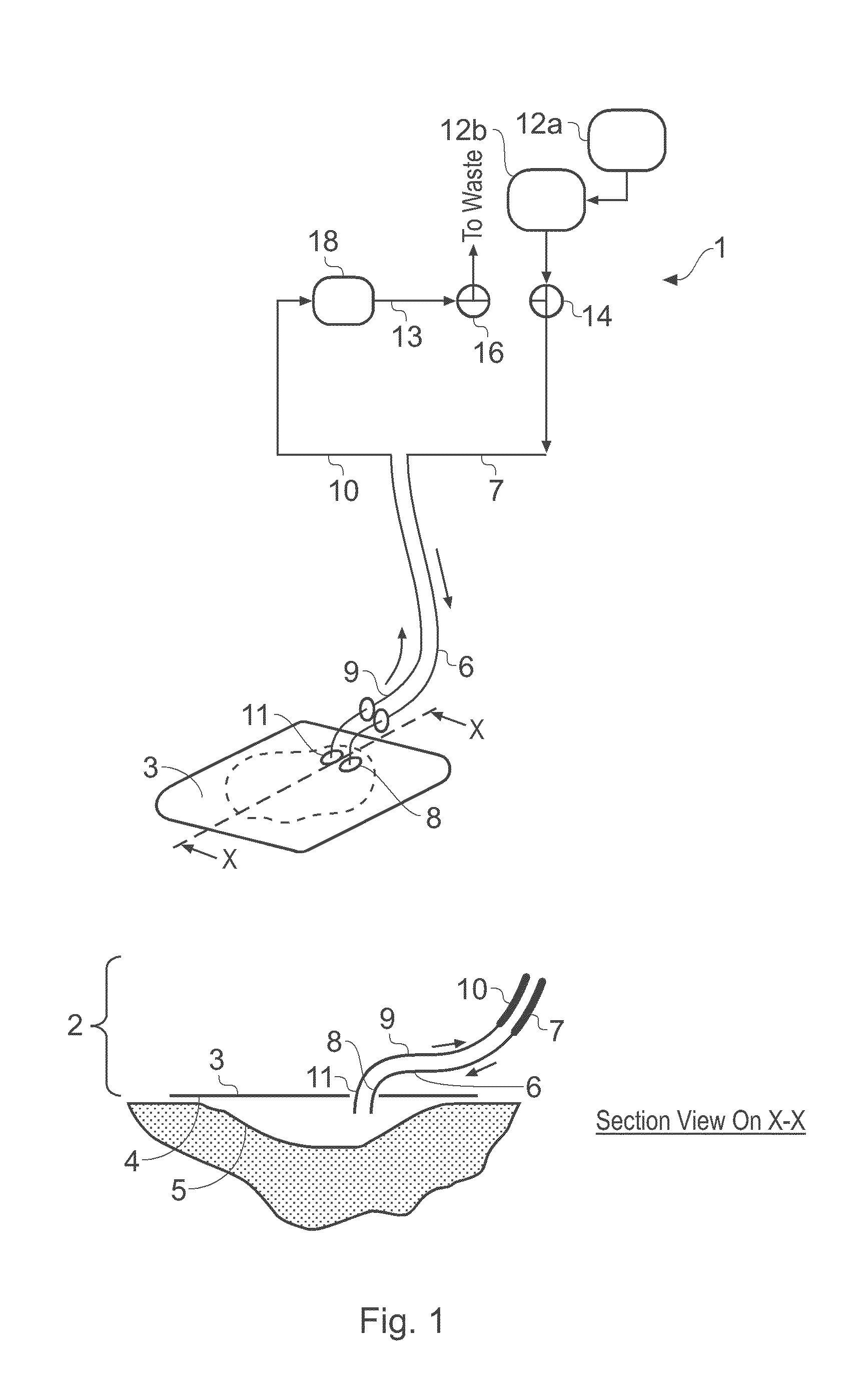
[0627]In this example, a gelatine sheet laid in a cavity wound model represents wound proteins and derivatives to be removed by the two-pump apparatus. The dressing is essentially identical with that in FIG. 18, i.e. it comprises a circular backing layer and a lobed chamber in the form of a deeply indented disc much like a multiple Maltese cross or a stylised rose, defined by an upper impervious membrane and a lower porous film with apertures that deliver the irrigant fluid directly from the wound bed over an extended area.

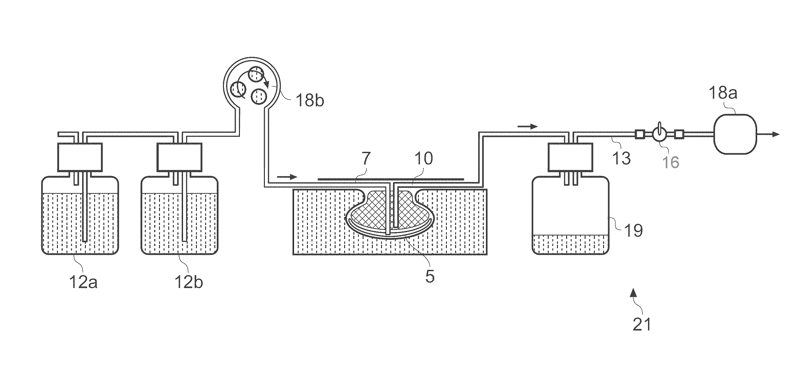
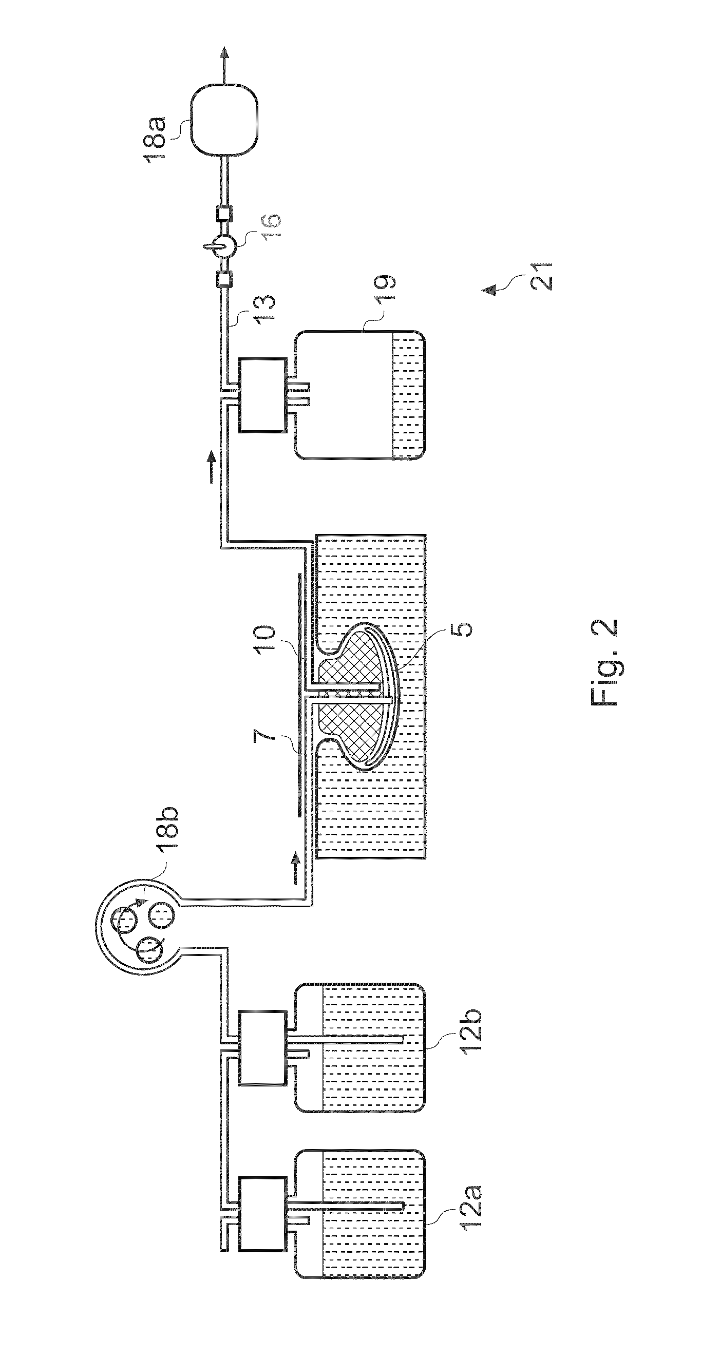
[0628]A two-pump system was set up essentially as in FIG. 2, with (a) an irrigant dispensing bottle—1000 ml Schott Duran, connected to (b) a peristaltic pump (Masterflex) for irrigant delivery, and associated power supply and supply tube, (c) a diaphragm vacuum pump (Schwarz) for aspiration, and associated power supply and offtake tube, connected to (d) a vacuum vessel (aspirate collection jar)—Nal...

example 2

[0649]The combination of simultaneous fluid flow (irrigation) and aspiration (under reduced pressure) on wound bed fibroblasts compared with the exposure of wound bed fibroblasts to repeated fill-empty cycles of fluid flow and aspiration.

[0650]An apparatus of the present invention was constructed essentially as in FIG. 33, which is an apparatus where an irrigant is delivered continually to the wound bed and the resultant wound exudate / fluid mixture is at the same time continually aspirated from the wound. Alternative systems are known where the wound is subjected to repeated iteration of a cycle of fluid delivery followed by a period of aspiration under reduced pressure.

[0651]The apparatus comprised a surrogate wound chamber (Minucells perfusion chamber) in which normal diploid human fibroblasts were cultured on 13 mm diameter (Thermanox polymer) cover slips retained in a two part support (Minucells Minusheets). Tissues present in the healing wound that must survive and proliferate ...

example 3

Removal of Wound Proteins and Heating a Wound with a Two-Pump Apparatus

[0659]In this example, a gelatine sheet laid in a cavity wound model represents wound proteins and derivatives to be removed by the two-pump apparatus.

[0660]The dressing is essentially identical with that in FIG. 28, i.e. a form of the dressing with an inlet pipe surrounded by an annulus of resistive conductive material, which is connected to a cell via a circuit with a current control and a switch, and generates thermal energy when a voltage drop is applied over it by the cell.

[0661]The inlet pipe communicates with the interior of an inlet manifold that distributes heated fluid directly to the wound when the dressing is in use.

[0662]A two-pump system is set up essentially as in FIG. 2, with an irrigant dispensing bottle—1000 ml Schott Duran, connected to a peristaltic pump (Masterflex) for irrigant delivery, and associated power supply and supply tube, a diaphragm vacuum pump (Schwarz) for aspiration, and associ...


PUM

PropertyMeasurementUnit
Pressureaaaaaaaaaa
Fractionaaaaaaaaaa
Fractionaaaaaaaaaa

Abstract

An apparatus and method for aspirating, irrigating and/or cleansing wounds is provided. The apparatus and method include one or more of the following: simultaneous aspiration and irrigation of the wound, supplying of thermal energy to fluid circulated through the wound; supplying physiologically active agents to the wound; a biodegradable scaffold in contact with the wound bed; and application of stress or flow stress to the wound bed.

Description

CROSS-REFERENCE TO RELATED APPLICATIONS[0001]This application is a continuation of U.S. application Ser. No. 14 / 496,305, filed Sep. 25, 2014, which is a continuation of U.S. application Ser. No. 14 / 012,164, filed Aug. 28, 2013, which is a continuation of U.S. application Ser. No. 12 / 976,949, filed Dec. 22, 2010, which is a continuation-in-part of U.S. application Ser. No. 10 / 599,722, filed Sep. 19, 2008, which is a National Phase of PCT International Application No. PCT / GB2005 / 001603, filed Apr. 27, 2005, designating the United States and published on Mar. 11, 2005 as WO / 2005 / 102415, which claims priority to Great Britain Patent Application No. 0409446.2, filed Apr. 28, 2004. U.S. application Ser. No. 12 / 976,949 is also a continuation-in-part of U.S. application Ser. No. 10 / 599,725, filed Sep. 22, 2008, which is a National Phase of PCT International Application No. PCT / GB2005 / 001595, filed Apr. 27, 2005, designating the United States and published on Oct. 11, 2005 as WO / 2005 / 105179,...

Claims


Application Information

Patent Timeline
IPC IPC(8): A61M3/02A61M5/44A61F13/00A61M1/00
CPCA61M3/0283A61M1/0058A61M1/0088A61M1/0092A61M5/44A61F2013/00357A61F13/00068A61M2205/3653A61M2205/368A61M2205/364A61M2205/3686A61F13/00063A61F7/034A61F13/0216A61F2007/0075A61F2013/00174A61F2013/00221A61F2013/00536A61F2013/0054A61N2005/0659A61N5/025A61N5/0616A61N5/0625A61N2005/0645A61F2007/0069A61M1/964A61M1/92A61M1/915A61M1/966A61M1/77A61M1/916A61M5/14A61F13/02A61M35/00A61M27/00A61M1/71
Inventor BLOTT, PATRICK LEWISHARTWELL, EDWARD YERBURYLEE-WEBB, JULIANNICOLINI, DEREKGREEN, CLAREMARTIN, ROBIN PAUL
Owner SMITH & NEPHEW INC
Why Eureka
Try Eureka