Light and lighting system

a technology of lighting system and light module, which is applied in the direction of general lighting, mass transit vehicle lighting, lighting support devices, etc., can solve the problems of inability to provide or arise gaps between light modules, unwanted lack of interior brightness, and unsightly effects on walls and ceilings, etc., and achieve the effect of improving the lighting system

Active Publication Date: 2017-01-05
DIEHL AEROSPACE GMBH
View PDF11 Cites 1 Cited by
  • Summary
  • Abstract
  • Description
  • Claims
  • Application Information

AI Technical Summary

Benefits of technology

[0004]The present invention relates to an improved light and an improved lighting system.

Problems solved by technology

With conventional systems, gaps between light modules can be provided or can arise that are caused by thermal expansion and tolerances.
Some gaps between light modules cause an unwanted lack of brightness in the interior, for example on the ceiling and walls thereof, i.e. regions that are not illuminated, as a rule strips.
Moreover, horizontal misalignments are possible, which produce unsightly effects on walls and ceiling, for example waves or steps.

Method used


Image

  • Light and lighting system
  • Light and lighting system
  • Light and lighting system

Examples


Embodiment Construction

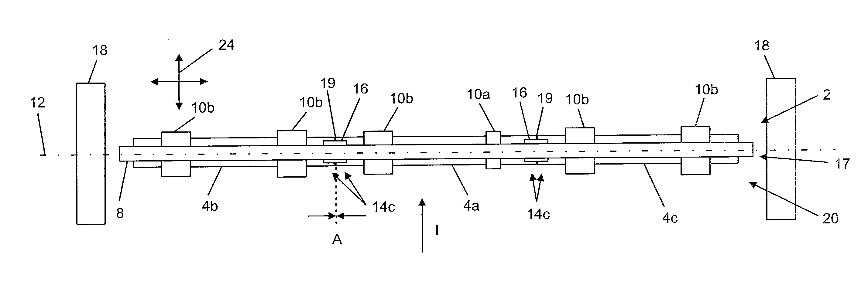
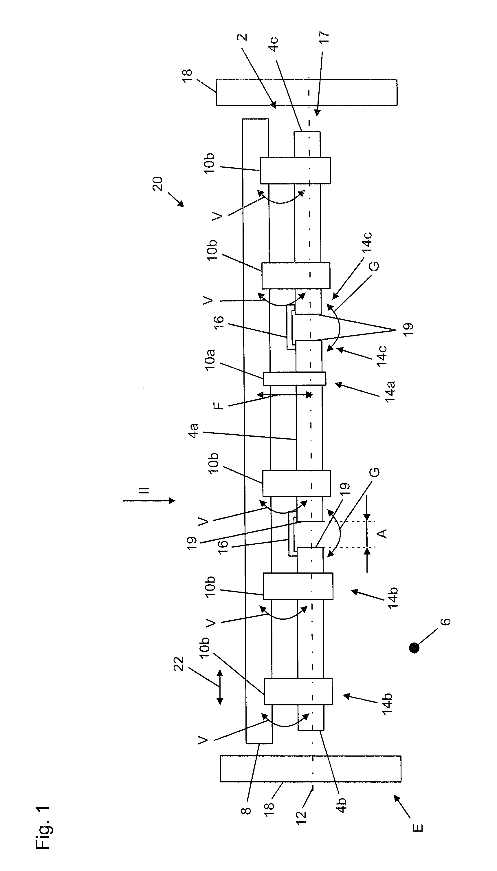
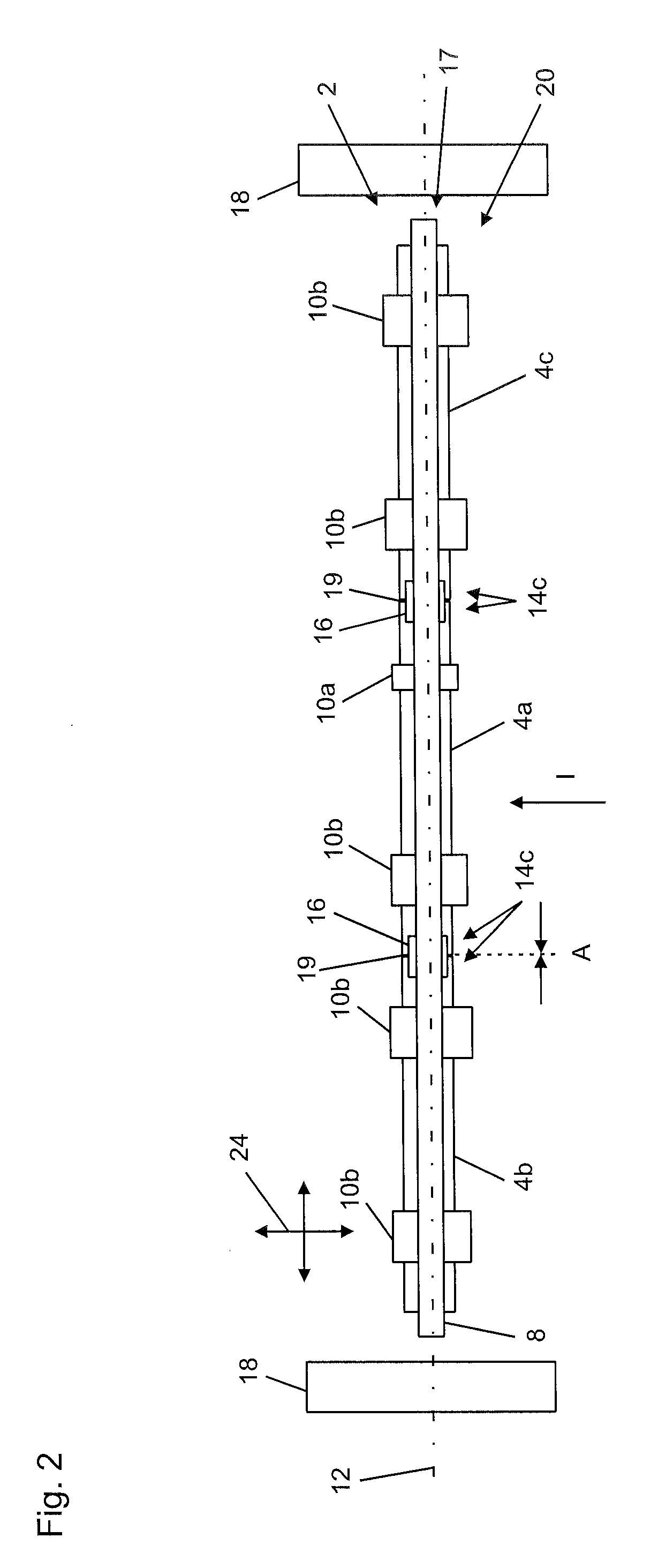
[0033]FIG. 1 shows a light 2 that contains a total of three light modules 4a-c. The light is installed in an interior 6 of a vehicle that is not illustrated further, in this case of an aircraft, and is located between two dividing walls 18 of the interior 6. The light 2 is disposed in an installed state E, and is thus mounted in the aircraft and ready for use.

[0034]The light 2 contains two joining arrangements 16, here in the form of clamps. Each of the joining arrangements 16 is used to join the respective adjacent light modules 4a and 4b or 4a and 4c to each other in a fixed mutual relative position G. Here too the relative position more precisely relates to the respective regions 14c or end segments of the light modules 4a-c that the joining arrangements 16 engage. The regions 14c face each other in the installed state E. Respective end faces 19 of the light modules 4a-c face each other. The joining arrangements 16 are in this case configured so that there is a certain non-zero d...


PUM


Abstract

A light for an interior of a vehicle contains at least two light modules that are disposed in series along a profile line and are mounted on a supporting structure in the vehicle. Each two adjacent light modules are attached to each other in regions. All light modules together form a light strip, which is attached to the supporting structure with exactly one first region, wherein a second region is movably supported on the supporting structure.
A lighting system contains a supporting structure and the aforementioned light.

Description

[0001]The present invention is directed a light for an interior of a vehicle, wherein the light contains at least two light modules. In an installed state, the light modules are mounted on a supporting structure of the vehicle and are disposed in series along a profile line.DISCUSSION OF THE PRIOR ART[0002]In vehicles, such as for example buses, trains and aircraft, a plurality of light modules are disposed one after the other in series, i.e. along a profile line, so as to produce light in the form of a strip of light. The light modules are mounted on a supporting structure that is in turn fixedly installed in the vehicle. With conventional systems, gaps between light modules can be provided or can arise that are caused by thermal expansion and tolerances. Some gaps between light modules cause an unwanted lack of brightness in the interior, for example on the ceiling and walls thereof, i.e. regions that are not illuminated, as a rule strips. Owing to manufacturing tolerances in the ...

Claims


Application Information

Patent Timeline
Patent Type & Authority Applications(United States)
IPC IPC(8): B60Q3/02F21V21/34F21V21/14F21V21/005B64D47/02B64D11/00
CPCB60Q3/0206B64D47/02B64D11/00F21V21/14B64D2011/0038B60Q3/025B60Q3/0289F21V21/34F21V21/005B60Q3/53B60Q3/43B60Q3/78
Inventor BERGELER, SWEN
Owner DIEHL AEROSPACE GMBH
Why Eureka
Try Eureka