Lighting system and method

a technology for lighting systems and lighting devices, applied in emergency power supply arrangements, lighting and heating equipment with built-in power, etc., can solve the problems of increasing the cost of installation of emergency lighting systems, increasing the cost of mains failure, and increasing the cost of emergency lighting systems. , to achieve the effect of reducing the cost and increasing the extent of emergency lighting systems

Inactive Publication Date: 2016-02-04
NICHOLLS LEE ANTHONY
View PDF2 Cites 3 Cited by
  • Summary
  • Abstract
  • Description
  • Claims
  • Application Information

AI Technical Summary

Benefits of technology

[0081]the ability to implement an emergency lighting system at a lower cost than existing hardwired emergency lighting systems;
[0082]future proofing by way of expandability, whereby the extent of an emergency lighting system can be increased by simply replacing standard light bulbs with removable light sources of the present application;

Problems solved by technology

One reason for this is that installing an emergency lighting system is prohibitively expensive in most situations.
The expense is more often than not due to the need for large battery banks and / or backup generators for powering the emergency lighting system when the mains power is no longer available.
Another issue with many emergency lighting systems is that a mains failure and switching system is required to detect the failure of the mains supply and to switch to supplying power to the lighting system by way of a secondary power source, such as batteries and / or generator(s).
However, this comes at the expense of separate wiring, light fittings and bulbs over the existing mains lighting circuit.

Method used


Image

  • Lighting system and method
  • Lighting system and method
  • Lighting system and method

Examples


Embodiment Construction

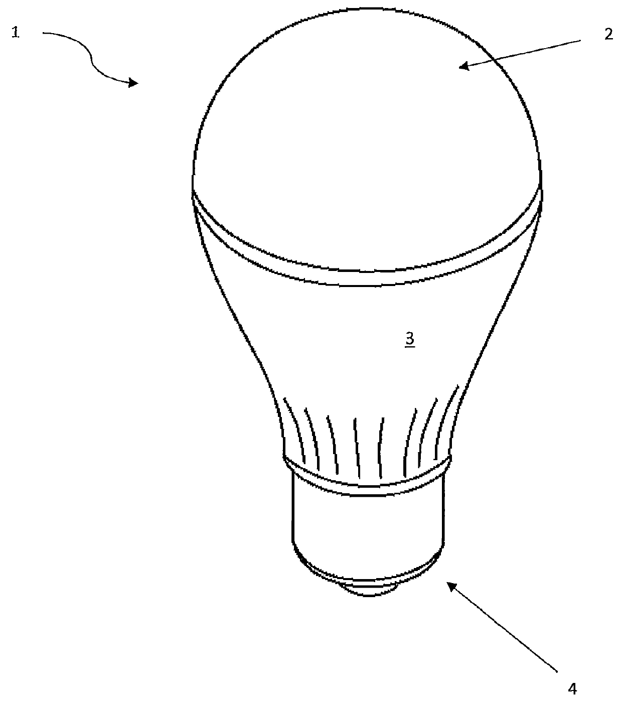
[0089]With respect to FIG. 1 there is shown removable light source as generally indicated by arrow 1. Removable light source 1 includes a light emitting source 2, a housing 3 which contains a secondary power source; and a control circuit (neither of which are shown in FIG. 1).

[0090]Removable light source 1 is configured to electrically connect to a mains lighting circuit by way of connector 4. Connector 4 may take the form of any one of many well known connector types, such as bayonet, screw in or pin types. The external configuration of the removable light source 1 shown in FIG. 1 should also not be seen as being limiting. The removable light source 1 could take any number of well known bulb form factors, such as MR12, MR16, standard globes or the like.

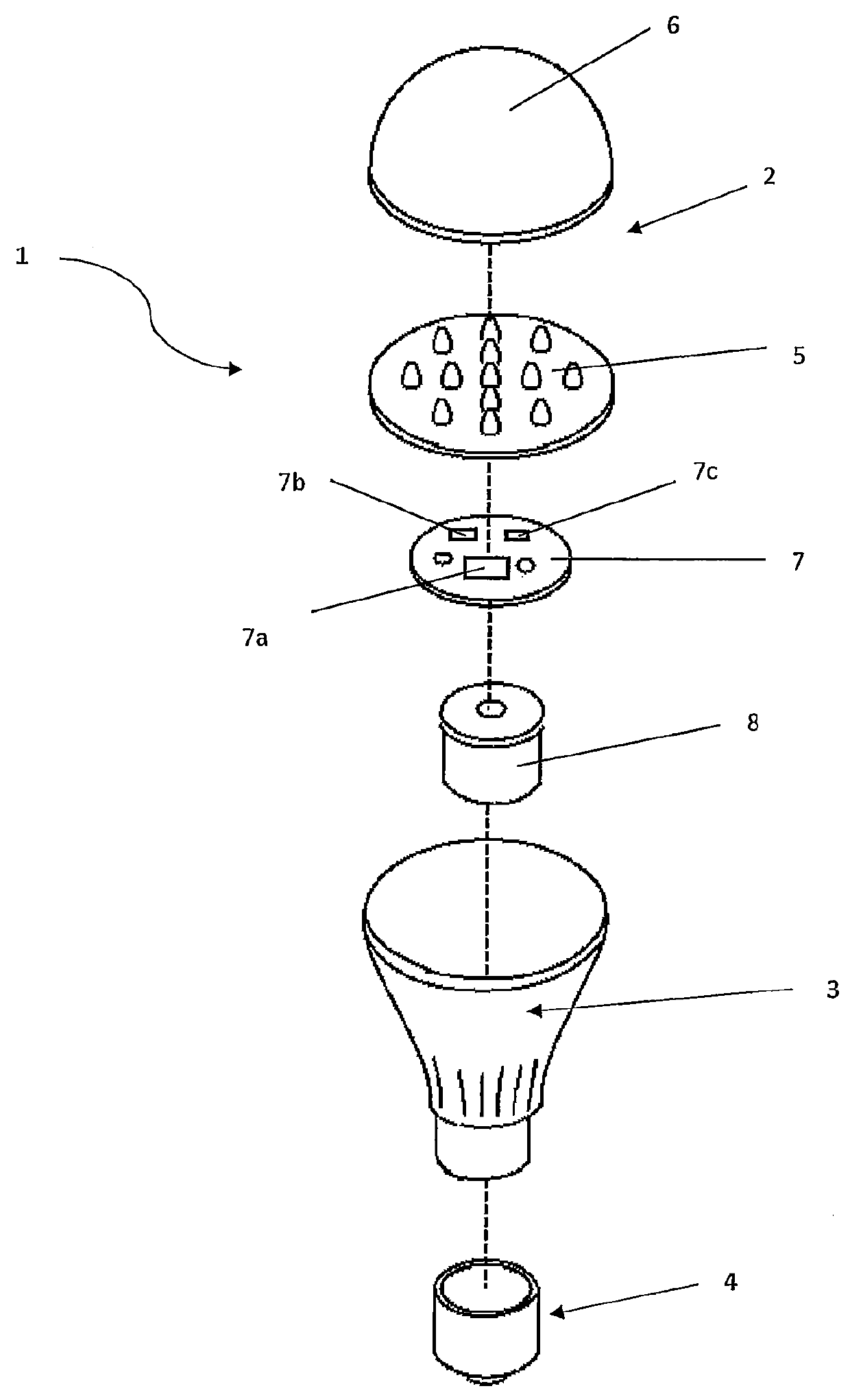
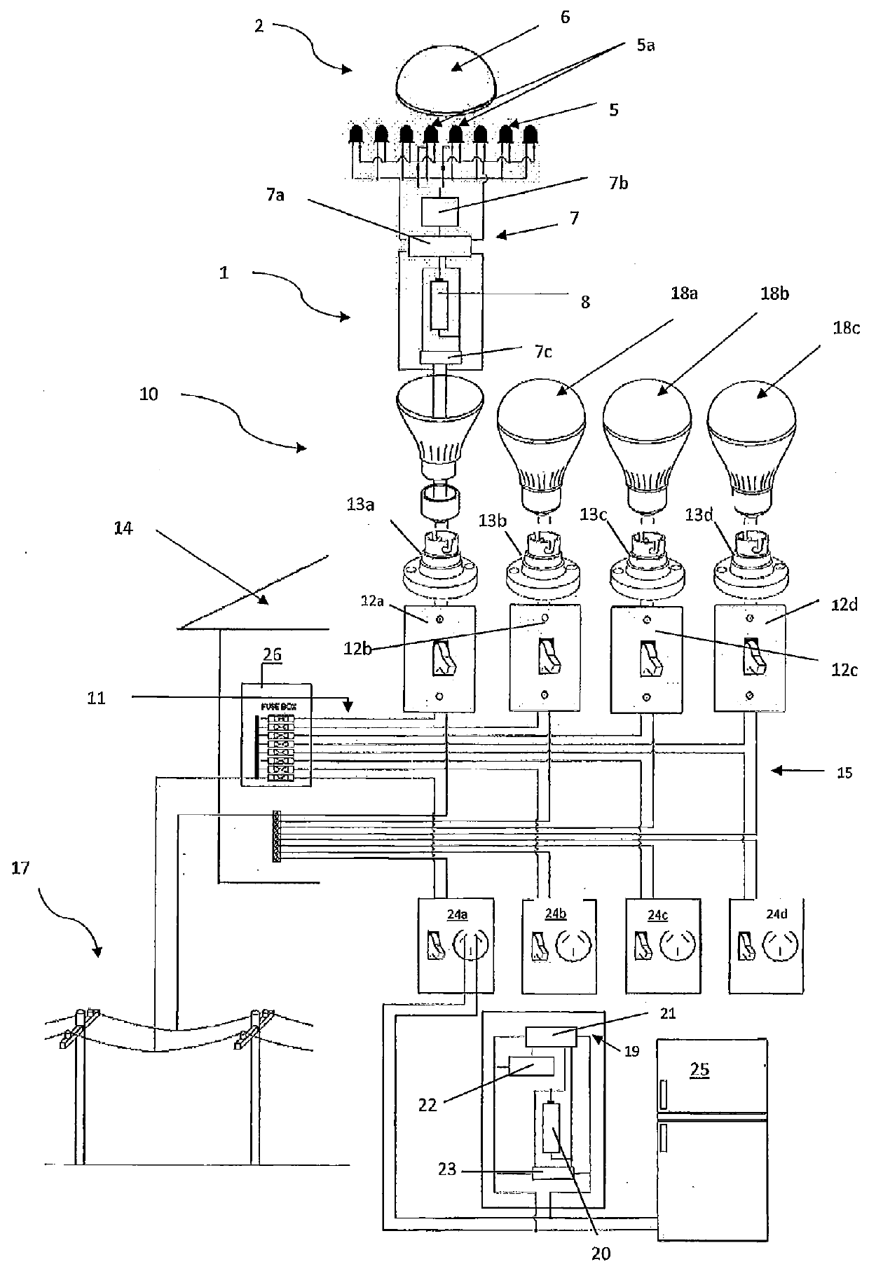
[0091]With respect to FIGS. 2 and 3 there is shown an exploded view of the removable light source 1 of FIG. 1. Removable light source 1 includes light emitting source 2 having cover 6. Enclosed within housing 3 are LEDs 5, control ci...


PUM


Abstract

According to one aspect of the present invention there is provided a removable light source including a light emitting source, a connector for electrically connecting the removable light source to a mains lighting circuit, a secondary power source and a control circuit configured to receive an on/off signal, whereby the control circuit is configured to power the light emitting source on if power is being supplied to the removable light source by the mains lighting circuit, OR power is provided by the secondary power source and the control circuit receives an on signal and power the light emitting source off if power being supplied to the removable light source by the mains lighting circuit ceases and the control circuit does not receive an on signal, OR power is being supplied by the secondary power source and the control circuit receives an off signal.

Description

STATEMENT OF CORRESPONDING APPLICATIONS[0001]This application is based on New Zealand Patent Application Number 608114, the entire contents of which are incorporated herein by reference.TECHNICAL FIELD[0002]The present invention relates to improvements in lighting systems and in particular to emergency lighting systems.BACKGROUND ART[0003]Emergency lighting systems are typically implemented in commercial buildings which have no source of natural light, or which house essential services, such as hospitals or the like. In other buildings only ‘Exit’ lighting indicating safe exit from a building may be powered from an emergency lighting system.[0004]One reason for this is that installing an emergency lighting system is prohibitively expensive in most situations. The expense is more often than not due to the need for large battery banks and / or backup generators for powering the emergency lighting system when the mains power is no longer available.[0005]Another issue with many emergency ...

Claims


Application Information

Patent Timeline
Patent Type & Authority Applications(United States)
IPC IPC(8): H05B33/08F21S9/02H02J9/06F21K99/00H05B44/00
CPCH05B33/0842F21K9/135F21S9/022H02J9/06F21Y2101/02F21K9/232F21Y2115/10H05B45/00
Inventor NICHOLLS, LEE ANTHONY
Owner NICHOLLS LEE ANTHONY
Why Eureka
Try Eureka