Device and method for failsafe monitoring of a moving machine part

a technology for moving machines and failsafe monitoring, applied in the field of machine and facility safety, can solve the problems of products and processes, time-consuming and costly repairs, and increasing the risk of people and products, and achieve the effect of cost-effective and flexibl

Active Publication Date: 2017-02-16
PILZ (COMPANY)
View PDF1 Cites 0 Cited by
  • Summary
  • Abstract
  • Description
  • Claims
  • Application Information

AI Technical Summary

Benefits of technology

[0010]It is an object to provide a device and a corresponding method which enable failsafe monitoring of a moving machine part of a technical facility which avoid the abovementioned disadvantages. In particular, it is an object to provide a device and a corresponding method which enable failsafe monitoring of a moving machine part of a technical facility in a simpler manner. It is further an object to provide such a device in a more cost-effective and flexible manner.

Problems solved by technology

However, many risks to persons, products, and processes arise from machines and facilities as a result of the rapid, high degree of automation, which are hardly recognizable at first glance.
In this way, on the one hand, parts of the technical facilities or the moving machine part itself can be entirely or partially damaged or destroyed, whereby time-consuming and costly repairs could become necessary.
On the other hand, a moving machine part exiting from its region of action can represent additional hazards to persons and products, which are not detected by the above-mentioned access monitoring.
In large facilities, for example, production lines in automobile manufacturing, in which a variety of technical facilities having moving machine parts have to be monitored, monitoring and the associated safety concept can become very complex and costly.
In addition, the monitoring of a region of action of a technical facility is becoming more and more complex as a result of increasingly intelligent machines, for example, computer-controlled, automatically operating robots, because the region of action thereof can often no longer be defined using clear boundaries.
In addition, in some fields of application, a use of simple position sensors at the boundaries of the region of action is not possible at all, for example, if a critical state first occurs after a movement region has been passed through multiple times. In particular in the case of circular movements about an axis, in which multiple complete revolutions are enabled, but a maximum number is predefined, monitoring using simple position sensors is not possible or is only to be managed using additional evaluation units, which in turn also have to be failsafe per se.

Method used


Image

  • Device and method for failsafe monitoring of a moving machine part
  • Device and method for failsafe monitoring of a moving machine part
  • Device and method for failsafe monitoring of a moving machine part

Examples


Embodiment Construction

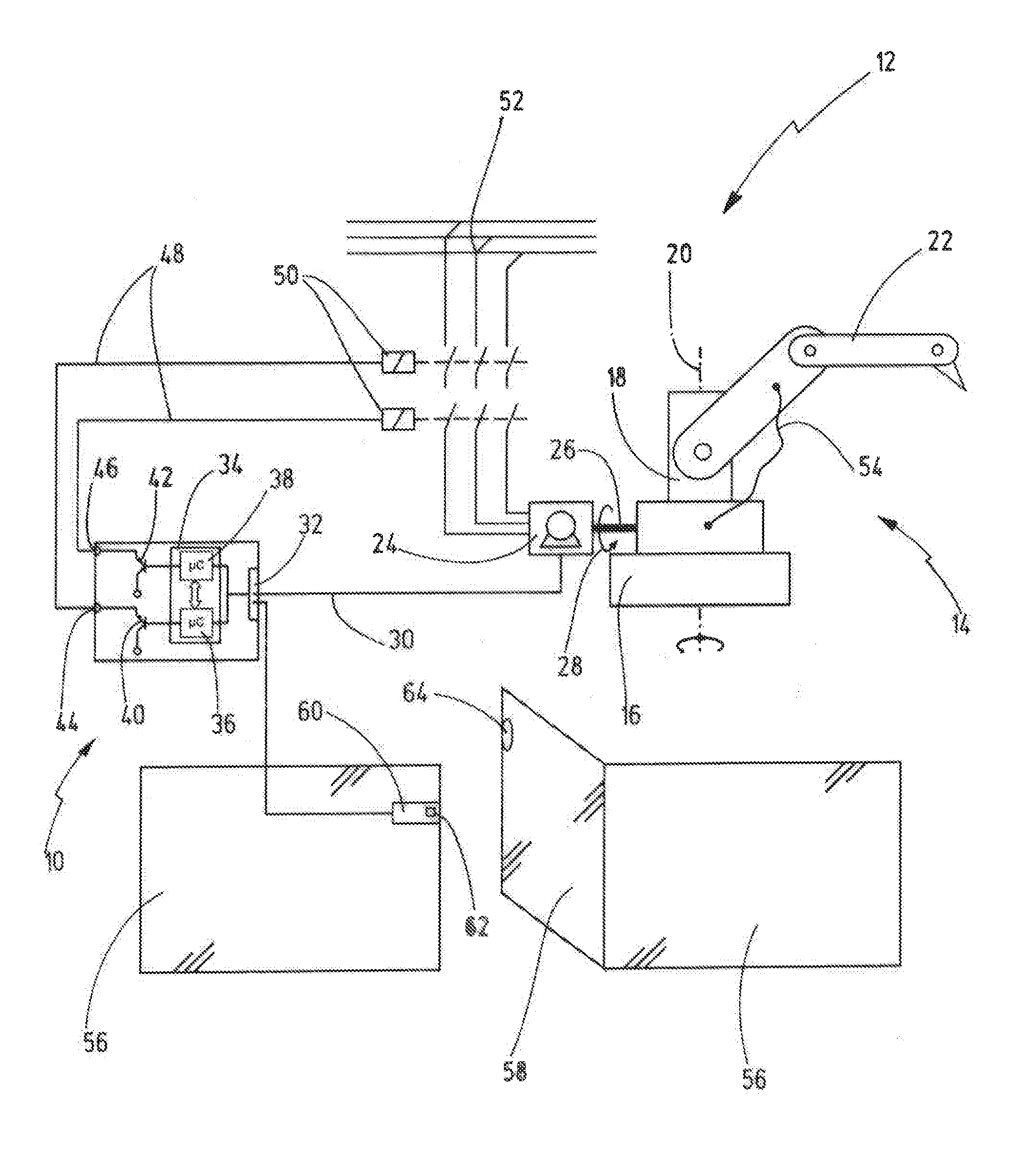
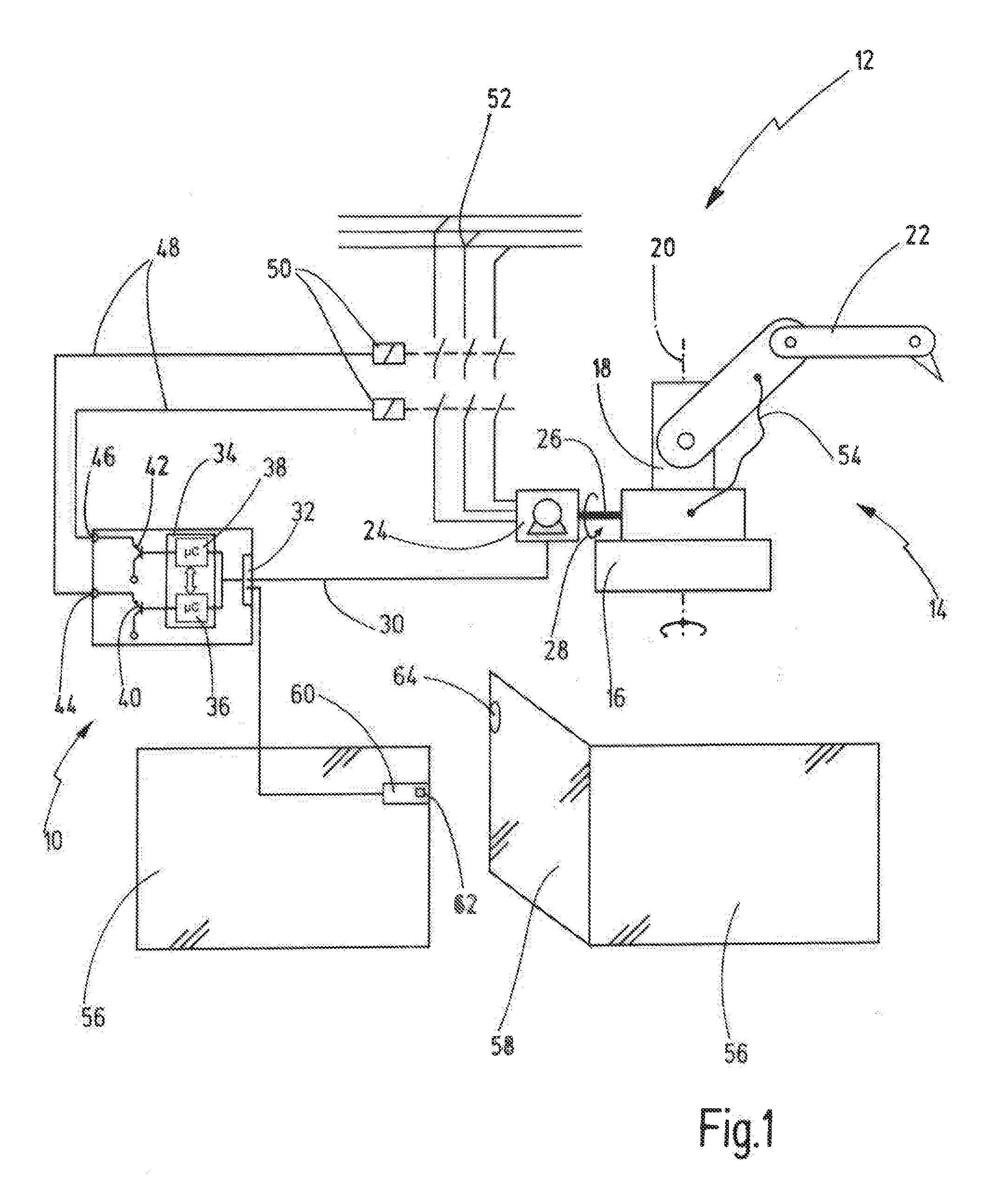
[0051]In FIG. 1, a preferred exemplary embodiment of the novel device is identified in its entirety with the reference numeral 10.

[0052]The device is used here to monitor a technical facility 12, which is indicated by a robot 14. The robot 14 is arranged here on a fixed base 16, on which a moving machine part 18 is placed, which can rotate here completely about its longitudinal axis 20. A robot arm 22, which is movable in space by the rotational movement of the moving machine part 18, is arranged on the moving machine part 18. The region of action to be secured of the technical facility therefore results here from the region of action of the robot arm 22 plus the area occupied by a moved load.

[0053]Two safety measures are applied in the illustrated case to secure the technical facility 12. On the one hand, it is monitored that no unauthorized access into the region of action to be secured occurs and, on the other hand, it is ensured that the technical facility 12 itself acts within ...


PUM


Abstract

A device for failsafe monitoring a number of passes of a moving machine part through a defined movement region comprising an input for receiving an encoder signal, which represents a motion value of the moving machine part. The device further comprises a failsafe evaluation unit for providing a failsafe shutdown signal as a function of the number of passes of the moving machine part through the defined movement region. The failsafe evaluation unit is configured to determine the number of passes of the moving machine part through the defined movement region from the motion value.

Description

CROSS-REFERENCES TO RELATED APPLICATIONS[0001]This application is a continuation of international patent application PCT / EP2015 / 059532, filed on Apr. 30, 2015 designating the U.S., which international patent application has been published in German language and claims priority from German patent application DE 10 2014 106 166.7, filed on May 2, 2014. The entire contents of these priority applications are incorporated herein by reference.BACKGROUND OF THE INVENTION[0002]The present disclosure relates to a device and method for failsafe monitoring a number of passes of a moving machine part through a defined movement region.[0003]The present disclosure relates in particular to the field of machine and facility safety. Generally, operating modern machines and facilities comes along with an extensive safety concept, no matter if it relates to machine tools such as processing centers, presses, assembly facilities or to robots. However, many risks to persons, products, and processes arise...

Claims


Application Information

Patent Timeline
Patent Type & Authority Applications(United States)
IPC IPC(8): G05B19/406G05B23/02
CPCG05B19/406G05B23/0291G05B2219/50198G05B2219/24182G05B2219/50177G05B2219/24008G05B9/02Y02P90/02H02H7/0844
Inventor SCHLECHT, MICHAEL
Owner PILZ (COMPANY)
Why Eureka
Try Eureka