Radar system having a clock pulse generator integrated into a central control unit

a clock pulse generator and radar technology, applied in the field of radar systems, can solve the problems of insufficient microcontroller technology for the required processing steps of the received radar wave, the inability to scale the processing power and memory size, and the disadvantages of the price, size and power loss of the radar sensor, so as to achieve cost-effective and scalable effect of capacity

Pending Publication Date: 2020-09-03
ROBERT BOSCH GMBH
View PDF7 Cites 0 Cited by
  • Summary
  • Abstract
  • Description
  • Claims
  • Application Information

AI Technical Summary

Benefits of technology

[0005]An object of the present invention is to provide a radar system for vehicles which is scalable in its capacity in a co

Problems solved by technology

Disadvantageous in this case is that the processing power and the memory size are relatively difficult to scale with regard to a greater performance.
This is a consequence in particular of the fact that based on a defined demand on the capacity, the microcontroller technology for the required processing steps of the received radar waves is no longer sufficient.
This may have a disadvantageous effect on the price, size and on power losses of a radar sensor.
In addition, the different used radar sensors usually have insufficient or lacking coherence.
In addition, a

Method used


Image

  • Radar system having a clock pulse generator integrated into a central control unit

Examples


Embodiment Construction

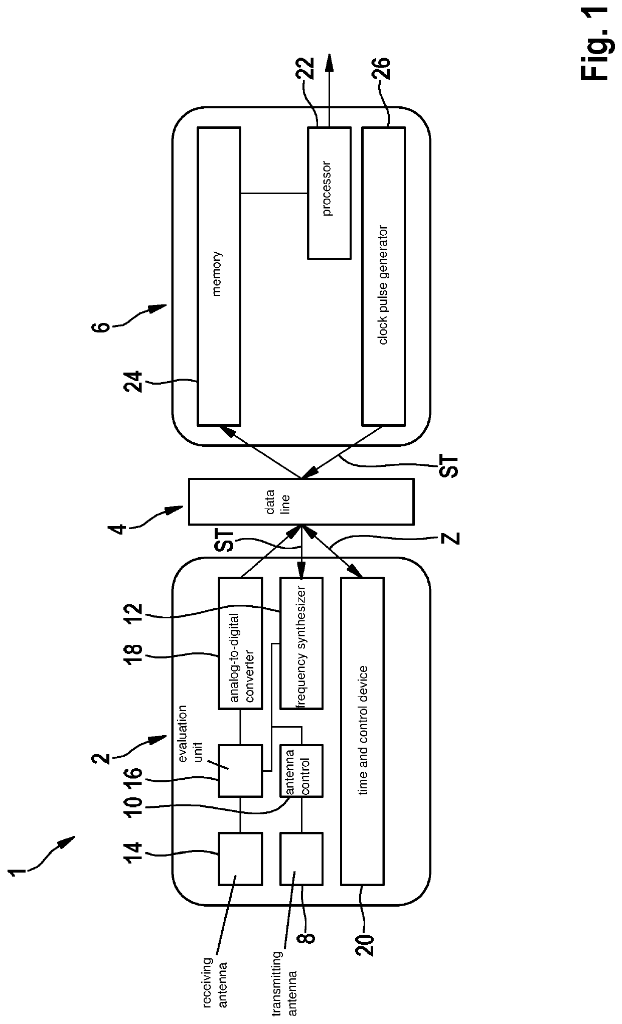
[0028]FIG. 1 shows a schematic illustration of an example radar system 1 according to a first specific embodiment of the present invention. Radar system 1 is made up of a radar sensor head 2, which is coupled via a data line 4 with a central control unit 6.

[0029]Radar sensor head 2 has at least one transmitting antenna 8, which is operable via an antenna control 10. Antenna control 10 is connected to a frequency synthesizer 12 for the generation of a carrier frequency of the radar waves.

[0030]Frequency synthesizer 12 receives a reference frequency through data line 4 from central control unit 6 via digitally transmitted control commands ST.

[0031]In addition, at least one receiving antenna 14 including a corresponding evaluation unit 16 for receiving radar waves is situated in radar sensor head 2. The received radar waves are able to be converted into digital measuring data by an analog-to-digital converter 18 and then be transmitted via data line 4 to central control unit 6.

[0032]A ...


PUM


Abstract

A radar system for a vehicle. The radar system has at least one central control unit for transmitting data and for processing received data, at least one radar sensor head, which is set apart from the central control unit and has at least one transmitting antenna for generating and at least one receiving antenna for receiving radar waves, and having at least one data line between the at least one central control unit and the at least one radar sensor head, with the at least one central control unit having a clock pulse generator for generating a reference frequency and the reference frequency being transmittable via the at least one data line to the at least one radar sensor head.

Description

FIELD[0001]The present invention relates to a radar system for a vehicle, which has a central control unit for transmitting data and for processing received data, at least one radar sensor head, which is set apart from the central control unit and has at least one transmitting antenna for generating and at least one receiving antenna for receiving radar waves, and at least one data line between the central control unit and the at least one radar sensor head.BACKGROUND INFORMATION[0002]In vehicles that offer a high degree of driver assistance functions or automated driving functions, an ever increasing number of radar sensors is installed. Through a greater number of radar sensors, a higher performance of the automated or semi-automated driving functions is meant to be achieved in comparison with individual radar sensors. Current solutions in this area are radar sensors which carry out extensive data processing of the received radar waves within the sensor. The radar sensors are thus...

Claims


Application Information

Patent Timeline
IPC IPC(8): G01S13/34G01S7/00G01S7/35G01S13/931
CPCG01S7/35G01S13/34G01S7/003G01S7/03G01S13/87G01S13/931G01S2013/9318G01S2013/9319G01S2013/93185
Inventor MAYER, MARCELSCHOOR, MICHAEL
Owner ROBERT BOSCH GMBH
Why Eureka
Try Eureka