Hand-held power tool

a power tool and hand-held technology, applied in the field of hand-held power tools, can solve the problems of not being percussion-resistant, affecting the performance of the tool, and the notch may be implemented, and achieve the effects of simple design, reliable torque limitation, and low cos

Active Publication Date: 2017-11-07
ROBERT BOSCH GMBH
View PDF9 Cites 0 Cited by
  • Summary
  • Abstract
  • Description
  • Claims
  • Application Information

AI Technical Summary

Benefits of technology

[0005]An object of the present invention is to make improvements over the above-mentioned disadvantages and to provide a hand-held power tool which has cost-effective, flexible, and reliable torque limiting, and which preferably has a simple design and is space-saving.
[0007]A hand-held power tool of this type includes a clutch housing of a torque clutch, and a planetary gear, situated in a gear housing, for transmitting a torque which is generated by a drive motor to a drive shaft. The clutch housing cooperates with the planetary gear via a pressure plate, the pressure plate being displaced in the axial direction in order to disengage the torque clutch. The axial relative motion of the pressure plate causes an axial relative motion between a switching element and an associated optical sensor, so that secure, reliable torque limiting may be ensured without overratcheting the torque clutch multiple times. Use of an optical sensor also saves space, so that the overall length and the overall width of the hand-held power tool do not have to be changed.
[0009]The switching element preferably protrudes into a closed-off area of the optical sensor via a gap seal, the optical sensor being accommodated in a recess in the clutch housing with little tolerance or essentially without play. Due to the gap seal, the closed-off area is sealed with respect to the clutch housing in such a way that the optical sensor is protected from dirt, so that secure, long-term functioning may be ensured. To ensure a low-tolerance accommodation of the switching element, the clutch housing also has a groove-shaped recess in which essentially play-free guiding of the switching element may be ensured. The manufacturing costs may advantageously be reduced considerably due to situating the closed-off area in a recess in the clutch housing, and also due to the groove-shaped recess for accommodating the switching element, since no additional installation space is necessary either for accommodating the switching element or for incorporating the optical sensor.
[0010]The clutch housing advantageously has a slider, it being possible for the slider to be pushed into the optical sensor in such a way that the axial relative motion between the switching element and the optical sensor is not detectable by the optical sensor. It is particularly advantageous that the slider has a switch so that the slider may be displaced via the switch. In this way the optical sensor may be continually disconnected so that mechanical overratcheting of the torque clutch is possible when the predefined torque is reached. The use of the hand-held power tool may thus be individually adapted and flexibly set by the user.
[0013]A fork light barrier is particularly advantageous as an optical sensor, since by using same, a relative motion of the switching element may be detected easily and quickly.
[0014]The pressure plate has an essentially circular design, thus enabling a space-saving, form-fit connection to the clutch housing.

Problems solved by technology

A disadvantage of the related art is that, at the torques to be transmitted, for strength reasons the notch on the pressure plate may be implemented only with a much greater width of the device.
The microswitches have a short service life, result in higher costs, are not percussion-resistant, and likewise require a larger housing for the hand-held power tool.

Method used


Image

  • Hand-held power tool
  • Hand-held power tool
  • Hand-held power tool

Examples


Embodiment Construction

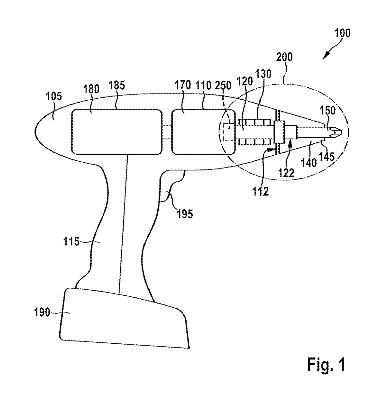
[0029]FIG. 1 shows a hand-held power tool 100 according to the present invention, which includes a housing 105 with a handle 115. According to the illustrated specific embodiment, hand-held power tool 100 is mechanically and electrically connectable to a battery pack 190 for supplying power off-grid. In FIG. 1, hand-held power tool 100 is designed as a cordless screw driller as an example. However, it is pointed out that the present invention is not limited to cordless screw drillers, and instead may find application using various hand-held power tools in which a tool is set into rotation, such as a cordless drill, a cordless percussion drill, a cordless screwdriver, or a percussion drill, etc.

[0030]An electric drive motor 180 which is suppliable with power from battery pack 190 and a gear 170 are situated in housing 105. Drive motor 180 is connected to a drive shaft 120 via gear 170. Drive motor 180 is situated in a motor housing 185 in the illustration, and gear 170 is situated in...


PUM

PropertyMeasurementUnit
torqueaaaaaaaaaa
strengthaaaaaaaaaa
widthaaaaaaaaaa

Abstract

A hand-held power tool is provided which includes a clutch housing of a torque clutch, and a planetary gear, situated in a gear housing, for transmitting a torque which is generated by a drive motor to a drive shaft. The clutch housing cooperates with the planetary gear via a pressure plate. The pressure plate is displaced in the axial direction in order to disengage the torque clutch. The axial relative motion of the pressure plate causes an axial relative motion between a switching element and an associated optical sensor, via which the drive motor may be switched off.

Description

FIELD OF THE INVENTION[0001]The present invention relates to a hand-held power tool, in particular a cordless screwdriver, a screw driller, or a cordless screw driller, including a tool carrier which is settable into rotation and drivable by a drive motor via a planetary gear.BACKGROUND INFORMATION[0002]Hand-held power tools which include a planetary gear, such as a cordless screwdriver, a cordless screw driller, or a drill, for example, generally include a safety clutch so that the hand-held power tool does not continue turning in an uncontrolled manner when a predefined torque is exceeded. A tool including a tool carrier which is settable into rotation is provided in German Published Patent Application No. 197 37 234, for example, the tool carrier being drivable by a drive motor via a planetary gear, and the annulus gear of the planetary gear cooperating with the gear housing via a friction clutch in such a way that a relative rotation of the annulus gear with respect to the gear ...

Claims


Application Information

Patent Timeline
Patent Type & Authority Patents(United States)
IPC IPC(8): B23B45/00B25F5/00B25B23/14
CPCB23B45/008B25F5/001B25B23/141B23B2270/48B25F5/00
Inventor KRAUS, MARTINROEHM, HEIKOHECHT, JOACHIM
Owner ROBERT BOSCH GMBH
Why Eureka
Try Eureka