Insert for a pneumatic tire

a technology of inserting and pneumatic tires, applied in the field of inserting pneumatic tires, can solve the problems of increasing vibration transmission to users, affecting the service life of users, and unable to provide lateral support to the sidewall of the tir

Active Publication Date: 2017-03-02
CUSHCORE INC
View PDF6 Cites 6 Cited by
  • Summary
  • Abstract
  • Description
  • Claims
  • Application Information

AI Technical Summary

Problems solved by technology

While such high pressures may provide increased rigidity to the sidewalls and tread, high pressures can simultaneously decrease tire traction and can result in increased transmission of vibration to a user, resulting in “stiff performance.”
Similarly, while pinch puncture preventing devices, such as disclosed in U.S. Pat. No. 5,679,184, may include inserts to radially displace an inflatable bladder from contacting a rim, they fail to provide lateral support to the sidewall of the tire, negating some of the benefits associated with use of reduced internal pressure within the tire.

Method used


Image

  • Insert for a pneumatic tire
  • Insert for a pneumatic tire
  • Insert for a pneumatic tire

Examples


embodiment 1

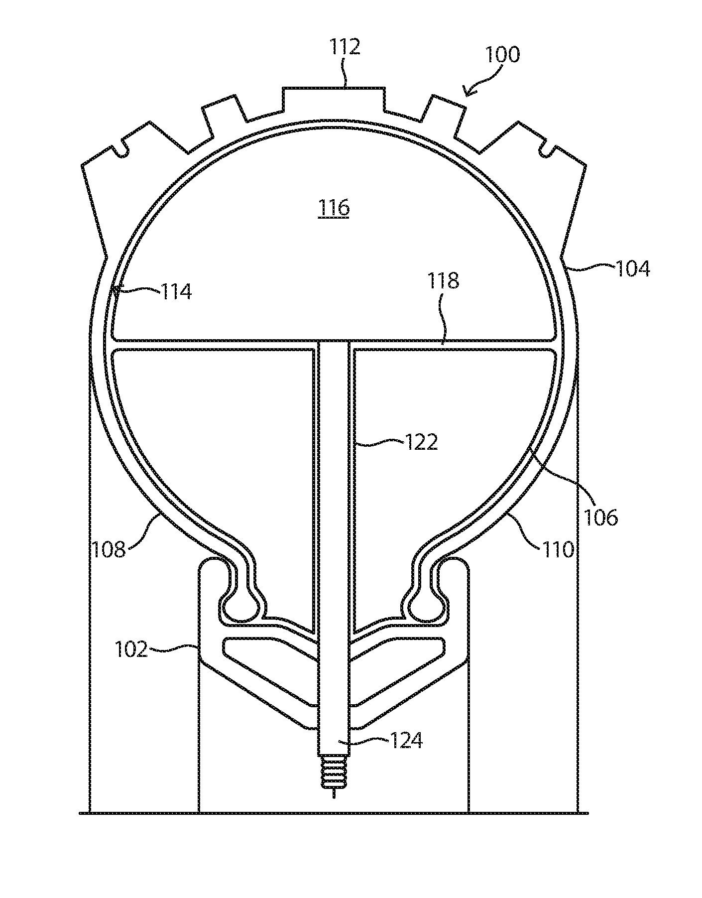
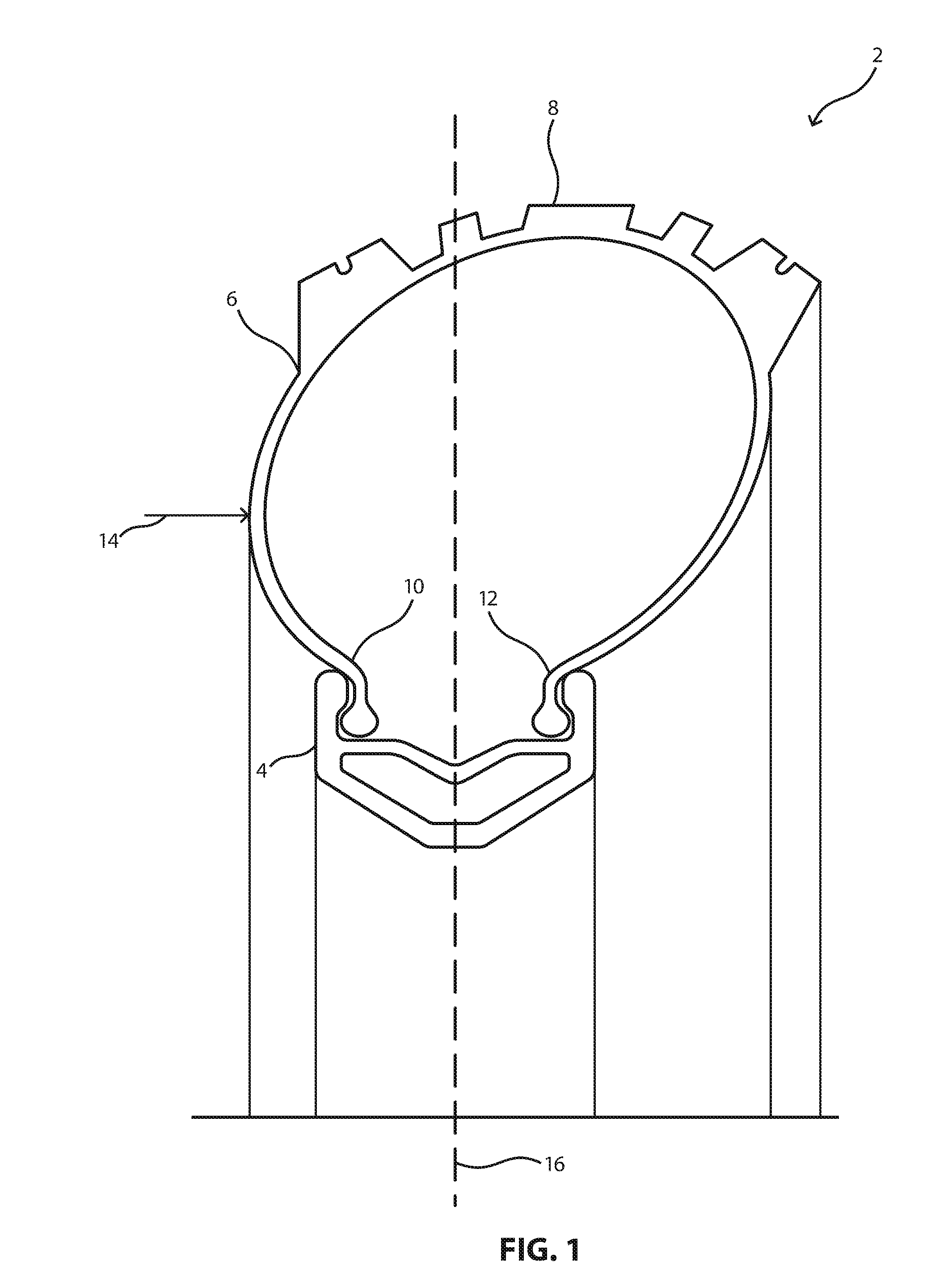
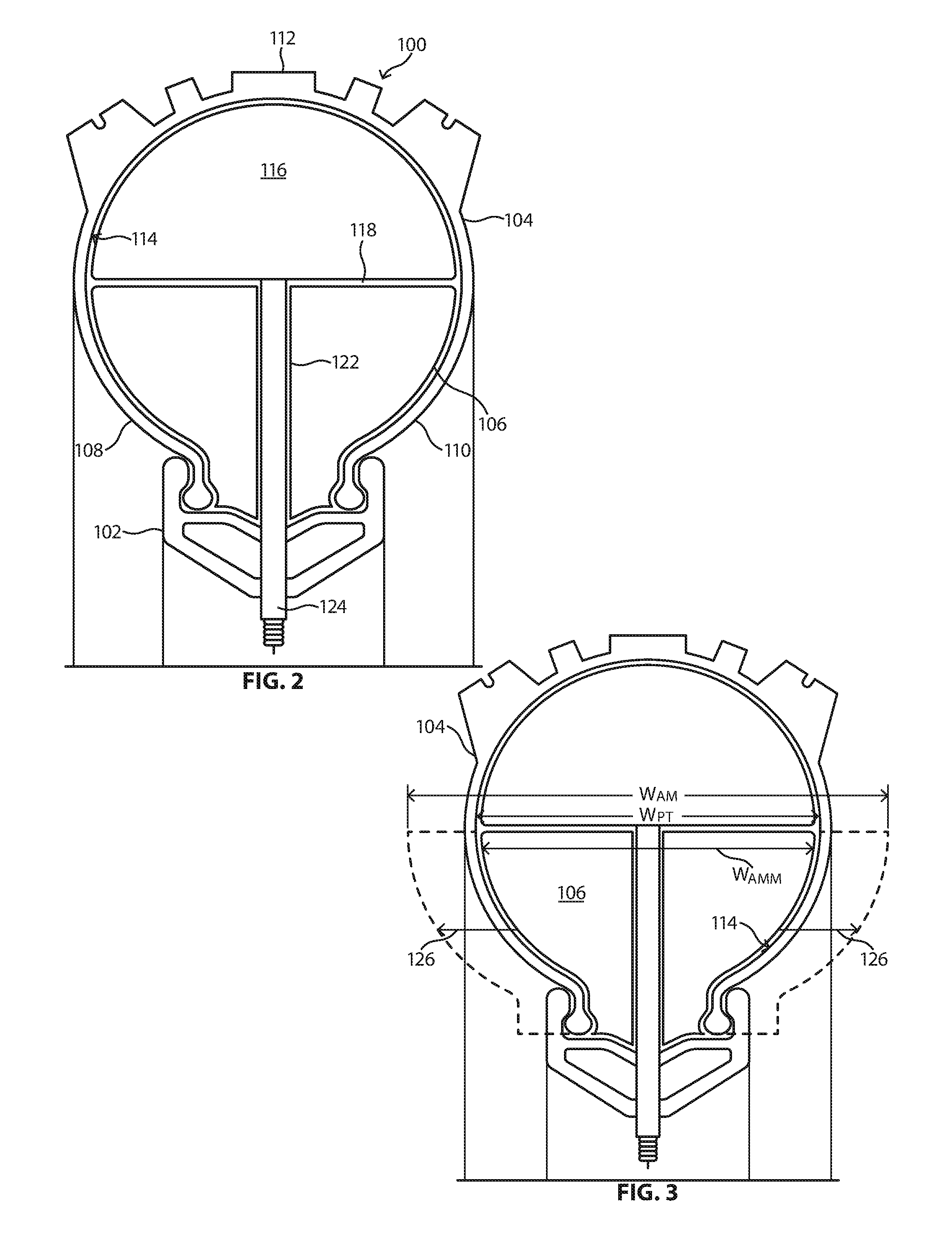
[0075]An insert for a pneumatic tire comprising:[0076]an annular member adapted to contact at least 10% of an interior surface of the pneumatic tire and provide an outward pressure thereagainst.

embodiment 2

[0077]An insert for a pneumatic tire comprising:[0078]an annular member adapted to contact at least 10% of an interior surface of the pneumatic tire and provide an outward pressure thereagainst; and[0079]an inflatable bladder disposed adjacent to the annular member.

embodiment 3

[0080]A tire assembly comprising:[0081]a pneumatic tire having an interior surface;[0082]an annular member contacting at least 10% of the interior surface and providing an outward pressure thereagainst.


PUM


Abstract

An insert for a pneumatic tire including an annular member adapted to contact at least 10% of an interior surface of the pneumatic tire and provide an outward pressure thereagainst.

Description

CROSS-REFERENCE TO RELATED APPLICATION(S)[0001]This application is a continuation in part of U.S. patent application Ser. No. 14 / 656,250, entitled “INSERT FOR A PNEUMATIC TIRE”, by Adam Krefting, filed Mar. 12, 2015, which claims priority under 35 U.S.C. §119(e) to U.S. Patent Application No. 62 / 056,308, entitled “INSERT FOR A PNEUMATIC TIRE”, by Adam Krefting, filed Sep. 26, 2014. This application also claims priority under 35 U.S.C. §119(e) to U.S. Patent Application No. 62 / 257,548, entitled “INSERT FOR A PNEUMATIC TIRE,” by Adam Krefting, filed Nov. 19, 2015.FIELD OF THE DISCLOSURE[0002]The present disclosure relates to tires, and more particularly to an insert for a pneumatic tire.RELATED ART[0003]Pneumatic tires typically have two sidewalls interconnected by an outermost tread. Radially innermost portions of the sidewalls are seated against a rim, forming a closed interior volume of the tire. Prior to use, the interior volume is pressurized to provide resistance against deformi...

Claims


Application Information

Patent Timeline
Patent Type & Authority Applications(United States)
IPC IPC(8): B60C17/01
CPCB60C17/01B60C2200/10B60C2200/12B60C5/08B60C5/002B60C17/065
Inventor KREFTING, ADAM
Owner CUSHCORE INC
Why Eureka
Try Eureka