Turbine inter-spool energy transfer system

Active Publication Date: 2017-03-02
SIKORSKY AIRCRAFT
View PDF3 Cites 4 Cited by
  • Summary
  • Abstract
  • Description
  • Claims
  • Application Information

AI Technical Summary

Benefits of technology

[0016]In accordance with additional or alternative embodiments, energy is transferred from the first spool to the second spool in order to increase available power without

Problems solved by technology

For such engines, an operational problem exists in that it is often the case that engine power will be limited by one parameter (e.g. speed or temperature) while having m

Method used


Image

  • Turbine inter-spool energy transfer system
  • Turbine inter-spool energy transfer system
  • Turbine inter-spool energy transfer system

Examples


Example

[0030]The detailed description explains embodiments of the disclosure, together with advantages and features, by way of example with reference to the drawings.

DETAILED DESCRIPTION OF THE DISCLOSURE

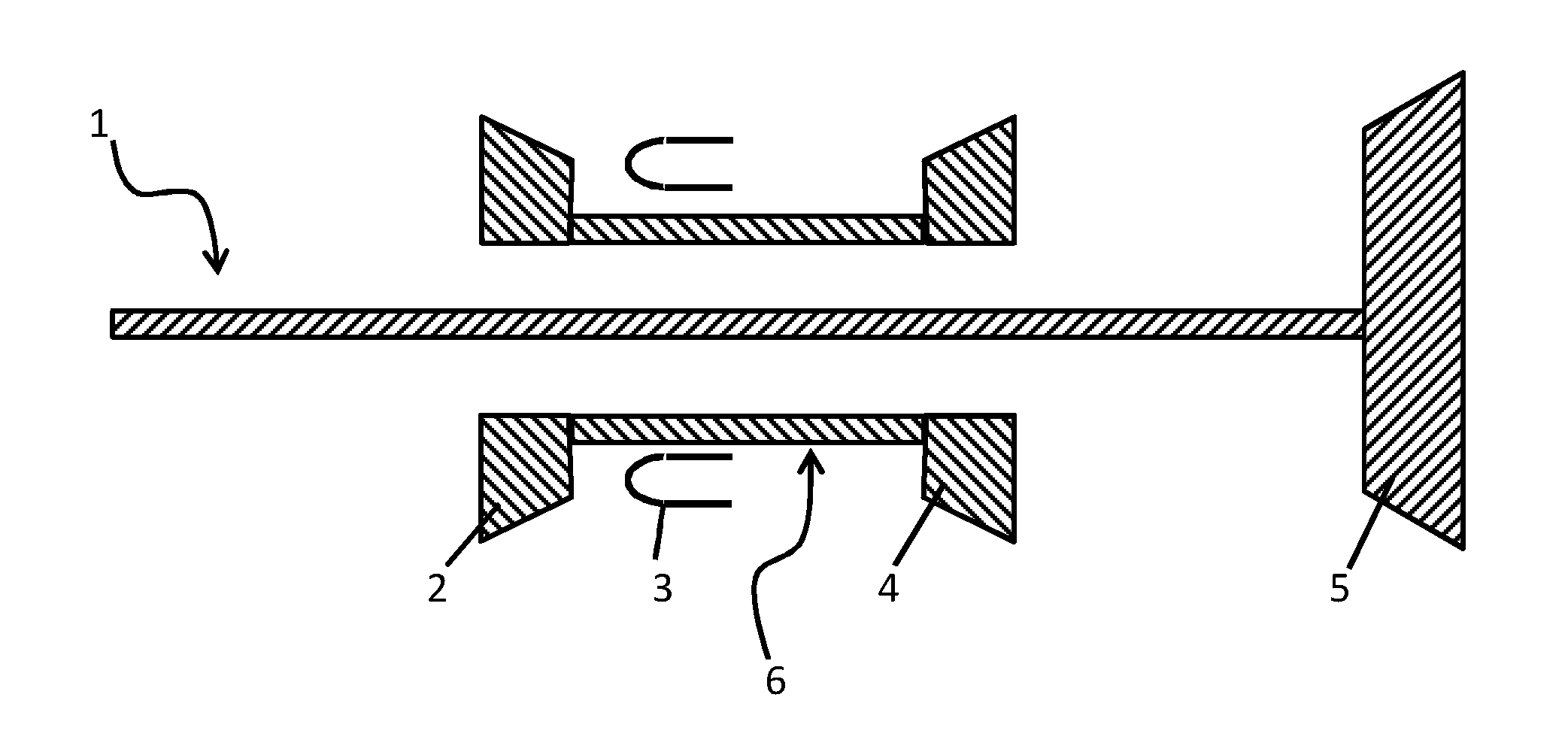
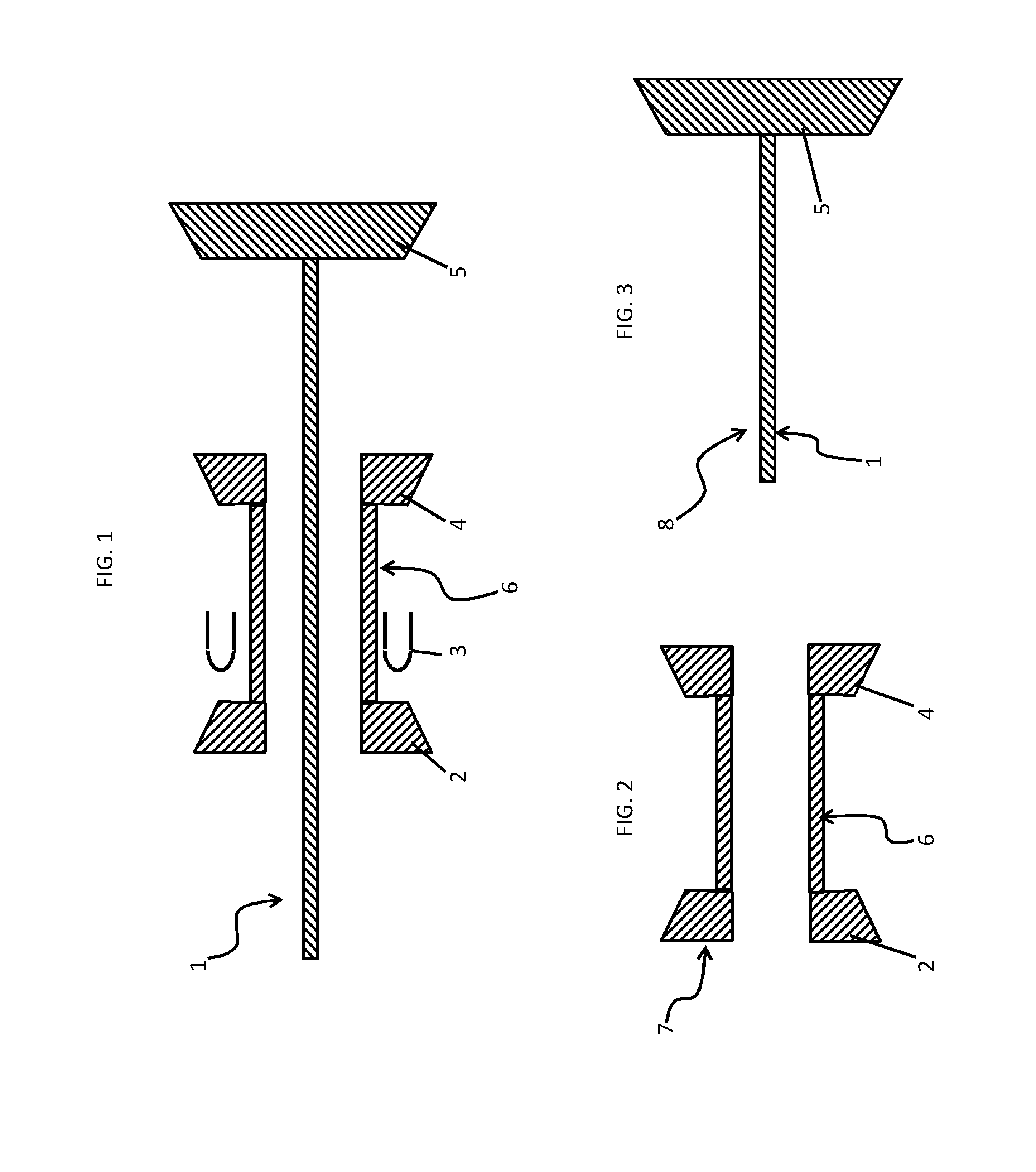
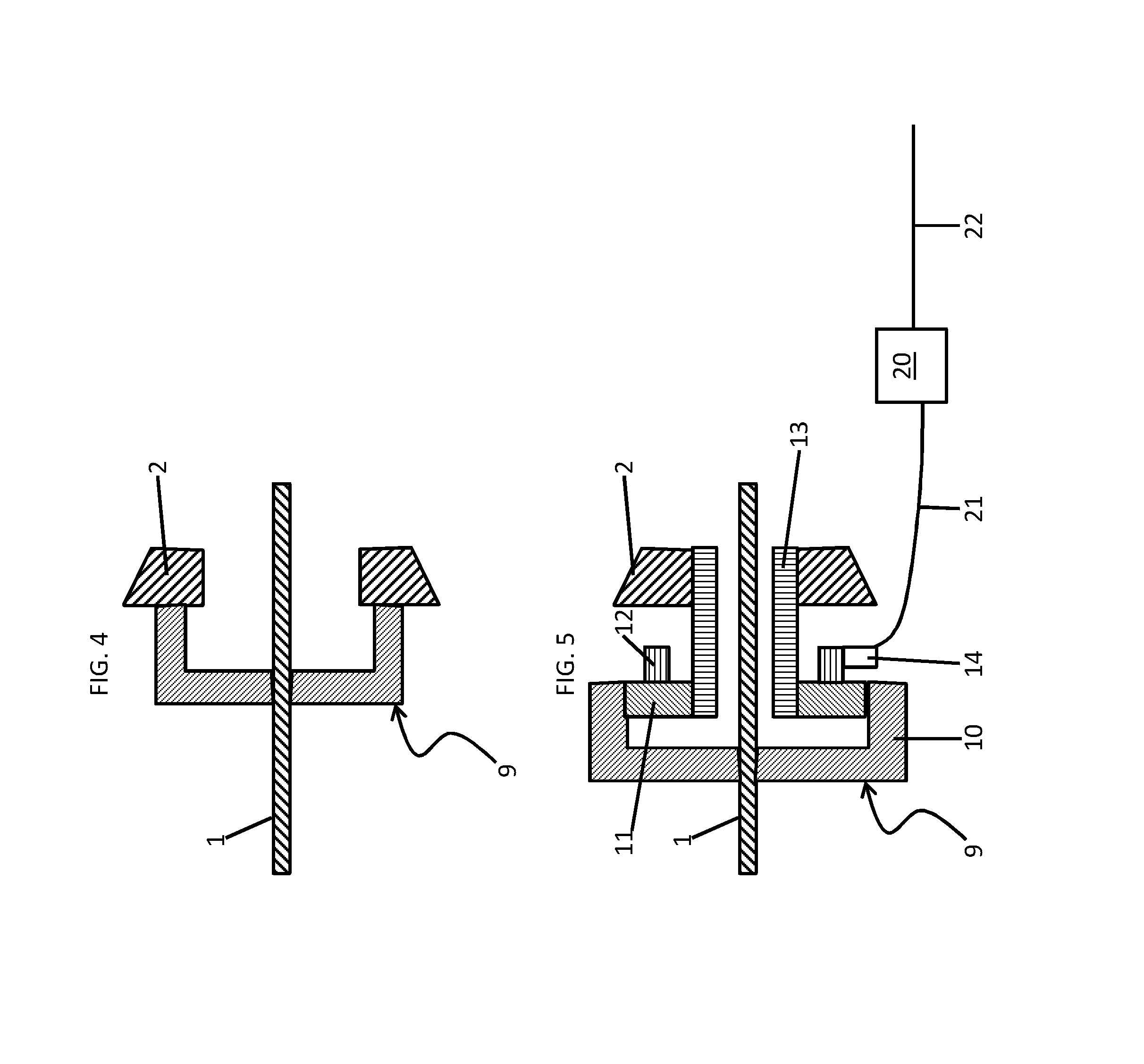
[0031]As will be described below, an inter-spool energy transfer system is provided for use with multi-spool engines to transfer energy between turbine stages in order to optimize overall engine performance (i.e., power, thrust, operating characteristics, etc.). The inter-spool energy transfer system may be usable for optimization of turbine performance for fixed wing (fan, prop, jet), rotary wing, ground vehicles (tanks, trains), electric power stations and / or any other end use which uses (primarily) multi-spool turbines. The inter-spool energy transfer system can make use of core load to slow down a free turbine (i.e., a gas generator turbine spool in a turbo-shaft engine) when the free turbine reaches its speed limit. This allows additional fuel to be added to the turbine until the engi...


PUM


Abstract

An inter-spool energy transfer system is provided and includes a first spool, a second spool, which includes components that are rotatable at a different speed as compared to components of the first spool and an inter-spool interface system coupled to at least one of the components of the first spool and at least one of the components of the second spool. The inter-spool interface system includes a controller, which is configured to supply power to one of the first and second spools and to draw power from the other of the first and second spools.

Description

CROSS-REFERENCE TO RELATED APPLICATIONS[0001]This application claims benefit of priority of U.S. Provisional Application No. 62 / 210,229 filed on Aug. 26, 2015, the disclosure of which is incorporated by reference.BACKGROUND OF THE DISCLOSURE[0002]The subject matter disclosed herein relates to an energy transfer system and, more particularly, to a turbine inter-spool energy transfer system.[0003]For multi-spool engines, whether those engines are provided in vehicles, aircraft or ground-based systems, the engines generally include a power shaft, a compressor or “gas generator”, a combustor, a gas generator turbine, a power turbine and a compressor shaft. During operation, inlet air is compressed in the gas generator to produce compressed air. This compressed air is then mixed with fuel and combusted in the combustor to produce a working fluid. The working fluid is directed to the gas generator turbine in which the working fluid is expanded to generate power that is used to drive rotat...

Claims


Application Information

Patent Timeline
IPC IPC(8): F02C7/36F01D15/12B64D41/00F02C3/04
CPCF02C7/36F02C3/04F01D15/12F05D2240/35F05D2220/32F05D2260/40311F05D2270/20B64D41/00F02C3/10F02C3/107F02C3/113F05D2220/329
Inventor WALTNER, PETER JAMESMONDELL, JR., TAD ARTHUR
Owner SIKORSKY AIRCRAFT
Why Eureka
Try Eureka