Object state identification method, object state identification apparatus, and carrier

a technology of object state identification and identification apparatus, which is applied in the field of object state identification method, object state identification apparatus, and carrier, can solve the problems of difficulty in achieving both target speed increase and target accuracy, and achieve the effect of identifying position and low calculation load

Active Publication Date: 2017-08-24
MURATA MASCH LTD +1
View PDF18 Cites 14 Cited by
  • Summary
  • Abstract
  • Description
  • Claims
  • Application Information

AI Technical Summary

Benefits of technology

[0018]According to various preferred embodiments of the present invention, it is possible to identify the position, posture, etc., of an object quickly and easily, even along with accuracy, under low calculation load.

Problems solved by technology

In the conventional method, there is a trade-off between the speed increase and the accuracy, meaning that it is difficult to achieve both a target speed increase and a target accuracy.

Method used


Image

  • Object state identification method, object state identification apparatus, and carrier
  • Object state identification method, object state identification apparatus, and carrier
  • Object state identification method, object state identification apparatus, and carrier

Examples


example 1

Of Position Identification Method

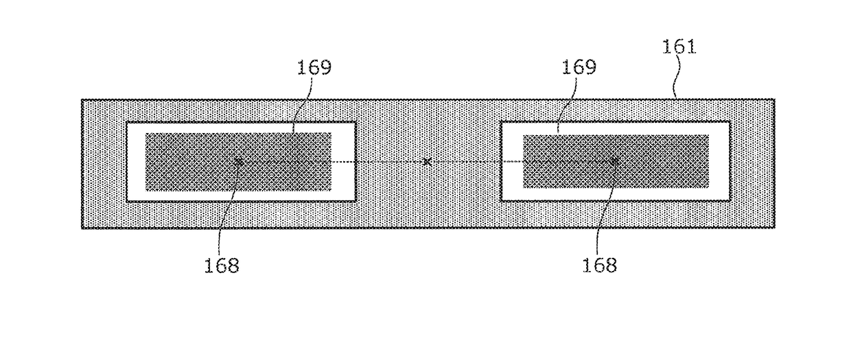
[0060]First, temporary points are generated at random in the virtual plane determined by the virtual plane determination calculator 161. Next, the temporary points that are located near the stable points are removed. As a result of the removal, a remaining point group 169 preferably has a shape as illustrated in FIG. 6. Next, the centroid (the center) of the remaining point group that is made up of the remaining temporary points is calculated. The position of the calculated centroid (the calculated center) is a center position 168 of the opening 210.

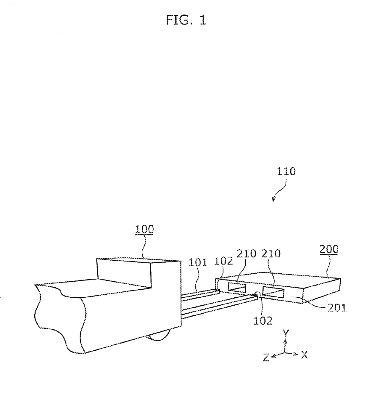
[0061]In the present preferred embodiment, the object 200, which is a pallet, preferably includes two openings 210 in the flat portion 201. The two openings 210 are arranged in a plane parallel or substantially parallel to the plane (the floor surface) on which the object 200 is placed. Therefore, the position identifier 164 calculates center positions of the two respective openings 210 and identifies, as...

example 2

Of Position Identification Method

[0063]In the present preferred embodiment, the object 200, which is a pallet, preferably includes two openings 210 in the flat portion 201. The two openings 210 are arranged in a plane parallel or substantially parallel to the plane (the floor surface) on which the object 200 is placed, and have the same shape. Under the above premise, the position of the object 200 is identified based on the axis of line symmetry of the arrangement of the stable points.

[0064]First, temporary points are generated at random in the virtual plane determined by the virtual plane determination calculator 161. Next, the temporary points that are located near the stable points are removed. As a result of the removal, a remaining point group 169 is of a shape such as that illustrated in FIG. 7. The remaining point group is made up of the remaining temporary points. The maximum value y_max and the minimum value y_min of the remaining temporary points in the vertical direction...


PUM


Abstract

An object state identification method of identifying a position and a posture of an object by obtaining actual measured values, which are three-dimensional data, at points on a flat portion including an opening on a surface of the object by a sensor includes extracting a corresponding point value indicating the position of an edge of the opening based on a predetermined feature value, calculating a plane equation indicating a plane including the flat portion based on the corresponding point value to determine a virtual plane, extracting, as a stable point, an actual measured value that is in the virtual plane, and identifying the position, posture, etc., of the object based on the stable point.

Description

CROSS REFERENCE TO RELATED APPLICATIONS[0001]This application claims the benefit of priority to Japanese Patent Application No. 2016-032528 filed on Feb. 23, 2016. The entire contents of this application are hereby incorporated herein by reference.BACKGROUND OF THE INVENTION[0002]1. Field of the Invention[0003]The present invention relates to an object state identification method, an object state identification apparatus, and a carrier including an object state identification apparatus that identify the state of an object, such as the position and posture thereof. In particular, the present invention relates to an object state identification method, an object state identification apparatus, and a carrier, each of which identifies an object state indicating the position, posture, etc., of an object including a flat portion including an opening on a surface of the object when an automated guided carrier or the like holds the object.[0004]2. Description of the Related Art[0005]Various ...

Claims


Application Information

Patent Timeline
Patent Type & Authority Applications(United States)
IPC IPC(8): G06T7/73G06T7/60G06K9/46
CPCG06T7/73G06T2200/04G06T7/60G06K9/4604G06T2207/10028G06T7/75
Inventor IIDA, MASAOMIHASHIMOTO, MANABUTAKEI, SHOICHI
Owner MURATA MASCH LTD
Why Eureka
Try Eureka