Touch sensing display device and driving method thereof

A display device, touch position technology, applied in static indicators, optics, instruments, etc., can solve problems such as large storage capacity and long processing time, and achieve the effect of reducing processing time

Inactive Publication Date: 2009-06-17
SAMSUNG DISPLAY CO LTD
View PDF0 Cites 14 Cited by
  • Summary
  • Abstract
  • Description
  • Claims
  • Application Information

AI Technical Summary

Problems solved by technology

[0005] However, when several locations are touched at the same time, multiple sensing elements generate sensing signals within a short time interval, requiring long processing time and large storage capacity

Method used


Image

  • Touch sensing display device and driving method thereof
  • Touch sensing display device and driving method thereof
  • Touch sensing display device and driving method thereof

Examples


Embodiment Construction

[0050] In the following detailed description, only certain exemplary embodiments of the invention are shown and described as illustrations of the invention.

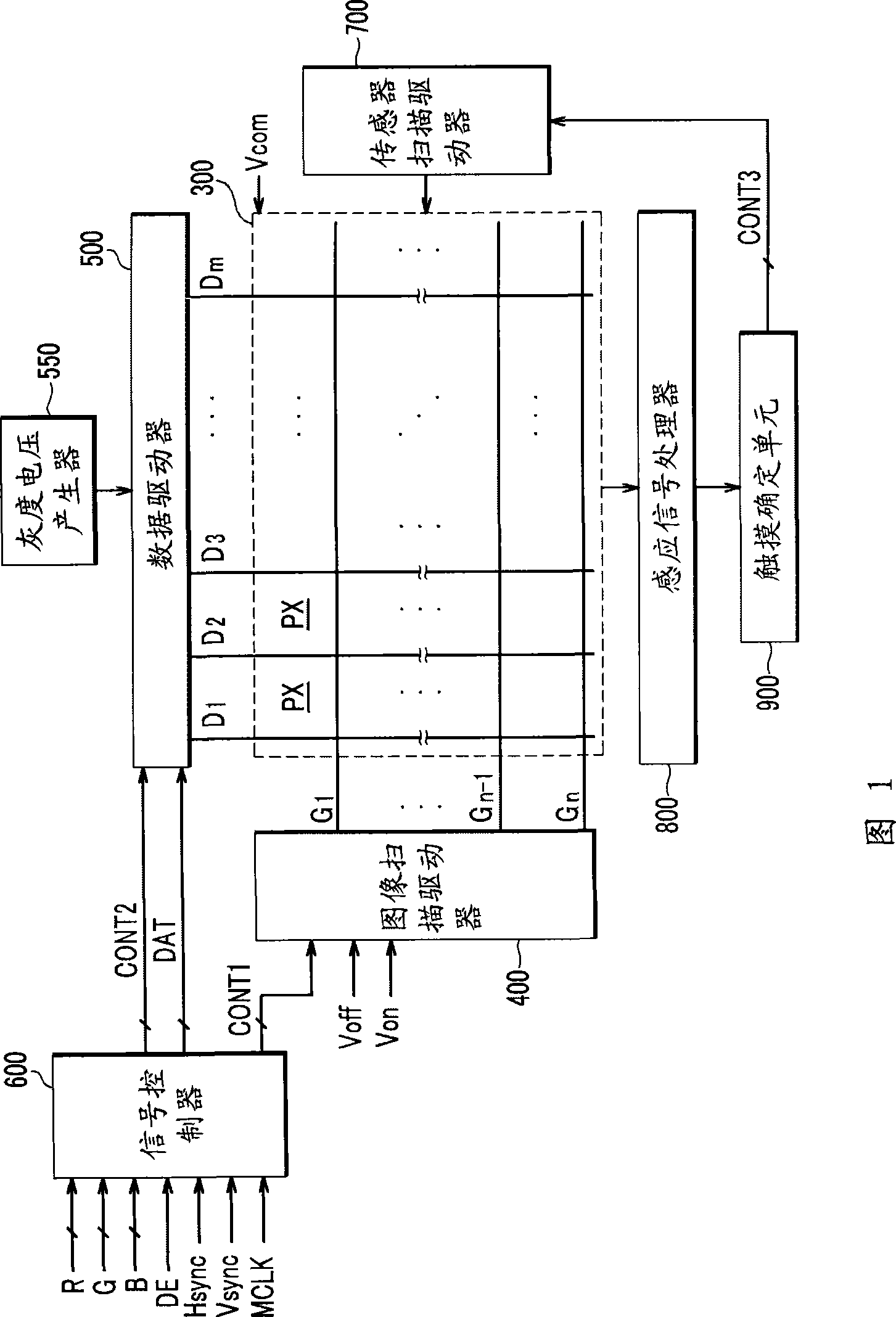
[0051] First, refer to Figure 1 to Figure 6 A touch-sensitive display device according to an exemplary embodiment of the present invention will be described in detail. Specifically, a liquid crystal display will be described as one example of a display device according to an exemplary embodiment of the present invention.

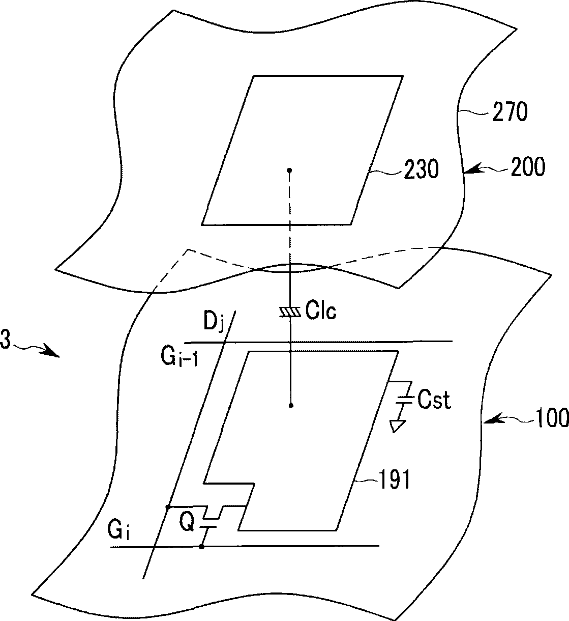
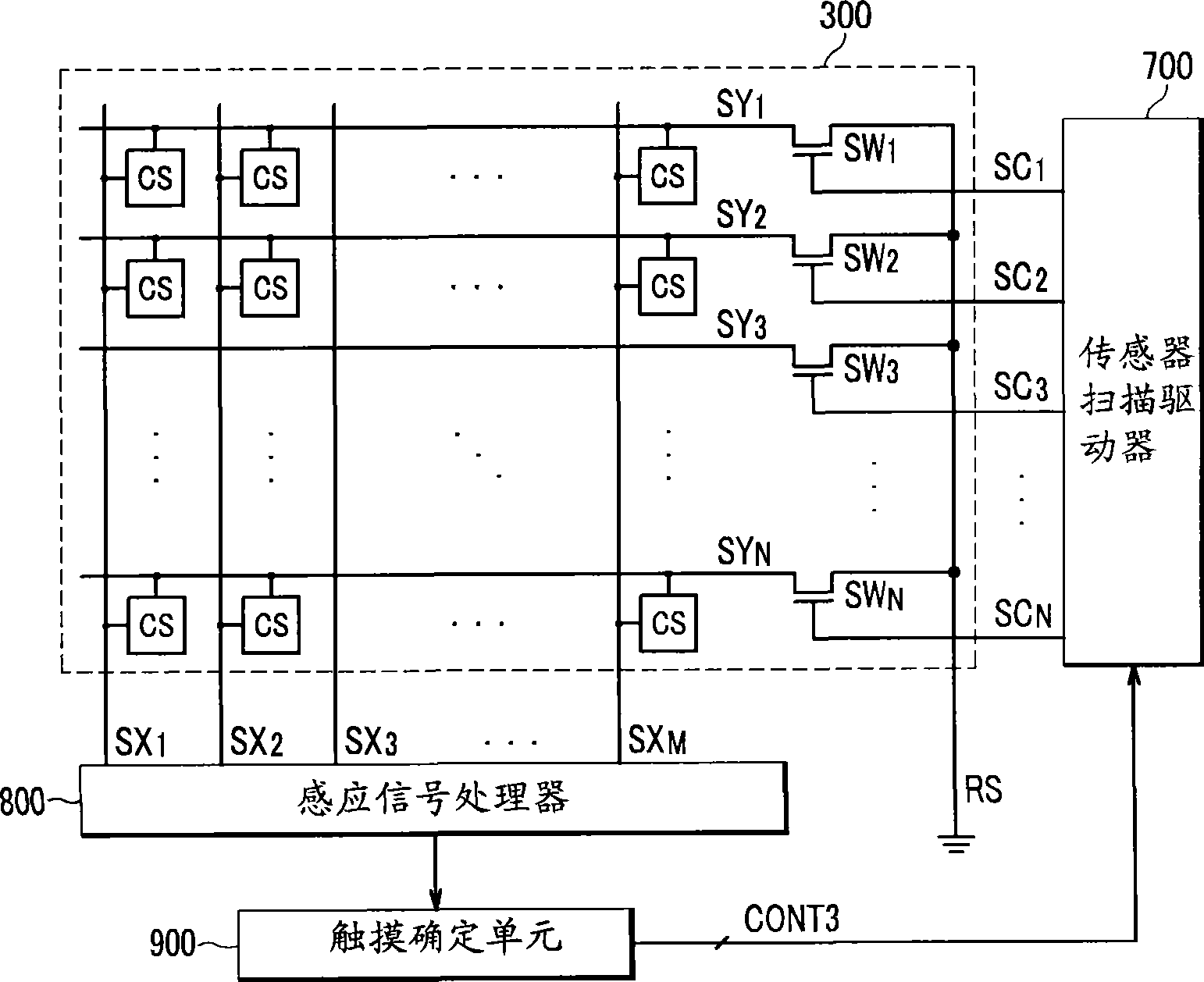
[0052] 1 is a block diagram of a liquid crystal display according to an exemplary embodiment of the present invention, figure 2 is an equivalent circuit diagram of one pixel in a liquid crystal display according to an exemplary embodiment of the present invention, image 3 is a block diagram of a part of a liquid crystal display according to an exemplary embodiment of the present invention, Figure 4 is an equivalent circuit diagram of an inductive element in a liquid crystal display according to a...


PUM


Abstract

In a touch sensing display device, a plurality of sensor scanning lines extend in a first direction and sequentially receive a first voltage, and a plurality of sensor data lines extend in a second, different, direction. A plurality of sensing elements are formed in regions defined by the sensor scanning lines and the sensor data lines, and each sensing element transmits the first voltage from a corresponding sensor scanning line to a corresponding sensor data line responsive to an external touch. A sensing signal processor converts voltages of the sensor data lines into sensing data, and, a touch determining unit processes the sensing data corresponding to the sensor scanning lines by at least one scanning line to determine positions of touch regions generated during at least one frame.

Description

technical field [0001] The invention relates to a display device and a driving method thereof. More specifically, the present invention relates to a touch-sensitive display device and a driving method thereof. Background technique [0002] In general, a display device includes a plurality of pixels arranged in a matrix, and displays an image by controlling light intensity of each pixel according to given luminance information. Specifically, the liquid crystal display device includes a pixel electrode display panel, a common electrode display panel, and a liquid crystal layer with dielectric anisotropy located between the two display panels. In a liquid crystal display, when a voltage is applied to two electrodes, an electric field is generated in the liquid crystal layer. The strength of the electric field can be adjusted to control the transmittance of light passing through the liquid crystal layer, thereby obtaining a desired image. [0003] Recently, products having se...

Claims


Application Information

Patent Timeline
Patent Type & Authority Applications(China)
IPC IPC(8): G06F3/041G09G3/36G02F1/133
CPCG06F3/0412G06F3/0416G06F3/04166G06F3/047G02F1/1335G02F1/133
Inventor 朴钟雄马元锡金炯杰李成雨李柱亨全丙起鱼基汉
Owner SAMSUNG DISPLAY CO LTD
Why Eureka
Try Eureka