
Rotor, whole pole module assembling method of rotor, replacement method and motor

A replacement method and rotor technology are applied in the manufacture of motor generators, stator/rotor bodies, electric components, etc., which can solve the problem of expensive maintenance costs, and achieve the effects of reducing maintenance costs, improving assembly efficiency and replacement efficiency.

Active Publication Date: 2018-11-23
BEIJING GOLDWIND SCI & CREATION WINDPOWER EQUIP
View PDF14 Cites 12 Cited by
  • Summary
  • Abstract
  • Description
  • Claims
  • Application Information

AI Technical Summary

Problems solved by technology

Once a permanent magnet or magnetic pole module is damaged, it is difficult to remove and replace the damaged permanent magnet or magnetic pole module one by one in the millimeter-level air gap space, and the generator can only be hoisted from the tower for repair. Considering the subsequent transportation , production, secondary hoisting costs, maintenance costs are very expensive

Method used


Image

  • Rotor, whole pole module assembling method of rotor, replacement method and motor
  • Rotor, whole pole module assembling method of rotor, replacement method and motor
  • Rotor, whole pole module assembling method of rotor, replacement method and motor

Examples


Embodiment Construction

[0038] Features and exemplary embodiments of various aspects of the invention will be described in detail below. In the following detailed description, numerous specific details are set forth in order to provide a thorough understanding of the present invention. It will be apparent, however, to one skilled in the art that the present invention may be practiced without some of these specific details. The following description of the embodiments is only to provide a better understanding of the present invention by showing examples of the present invention. In the drawings and the following description, at least some well-known structures and techniques have not been shown in order to avoid unnecessarily obscuring the present invention; and, for clarity, the dimensions of some structures may have been exaggerated. Furthermore, the features, structures, or characteristics described hereinafter may be combined in any suitable manner in one or more embodiments.

[0039] The orient...


PUM


Abstract

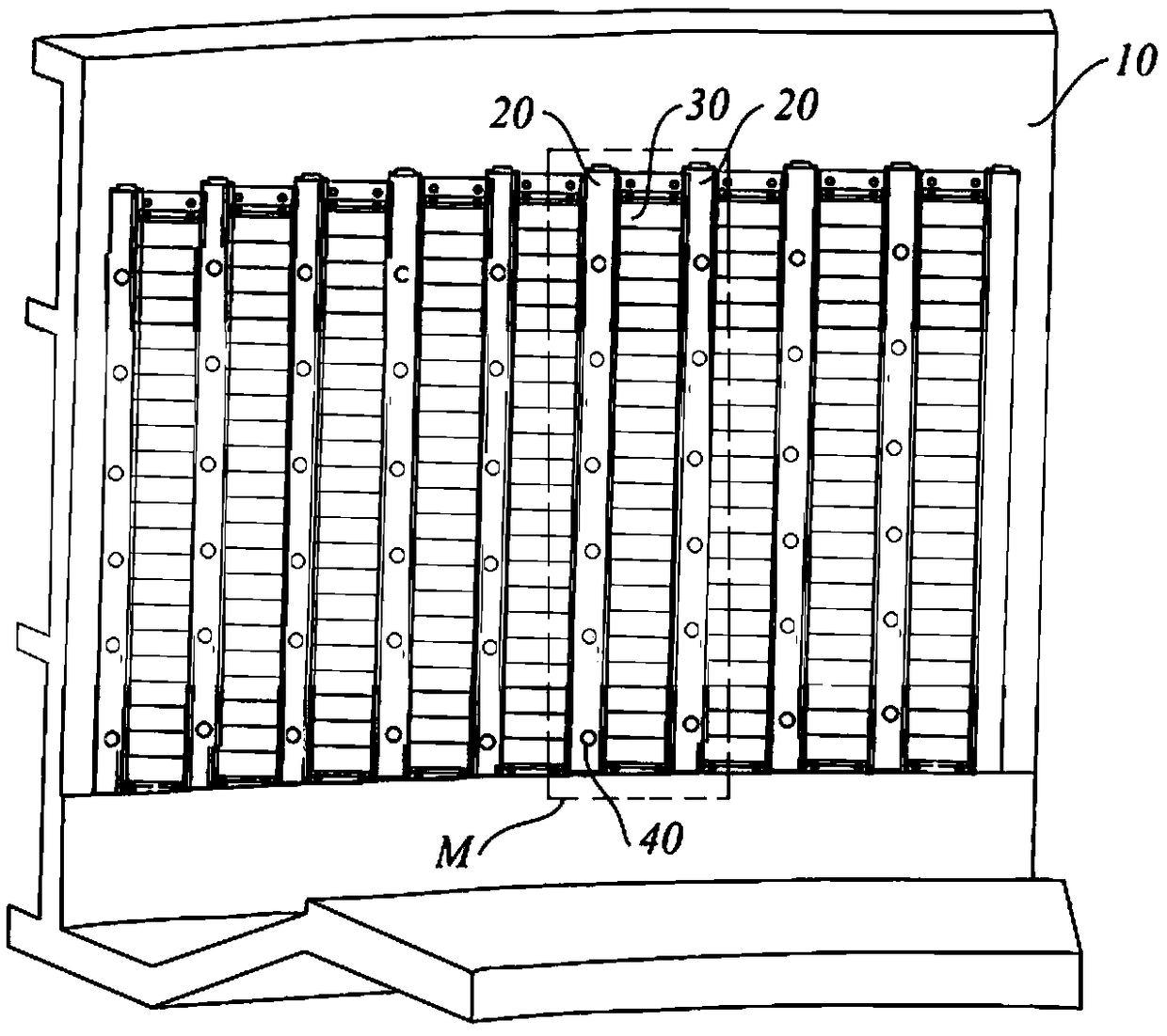
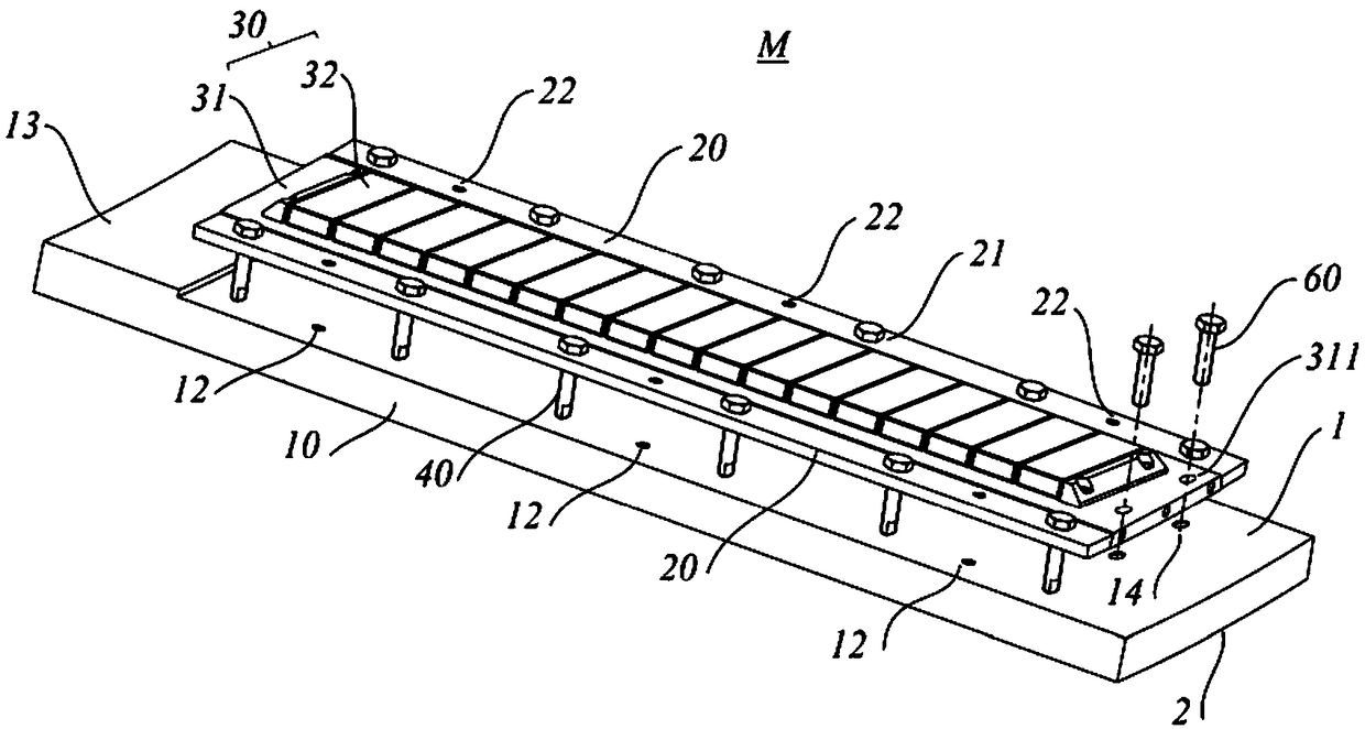
The invention relates to a rotor, a whole pole module assembling method of the rotor, a replacement method and a motor. The rotor is arranged on the outer peripheral surface of a motor stator in a sleeved mode, and comprises a rotor magnetic yoke, a plurality of pressing strips, a plurality of whole pole modules, and a plurality of fixed parts, wherein the rotor magnetic yoke is provided with an opposite mounting surface and outer peripheral surface in the radial direction; the plurality of pressing strips are distributed on the mounting surface at intervals along the circumferential directionof the rotor magnetic yoke, and the radial distance between each pressing strip and the mounting surface is adjustable; each whole pole module is detachably connected between every two adjacent pressing strips; the whole pole module comprises a carrier plate and a plurality of permanent magnets arranged on the carrier plate, wherein the carrier plate is attached to the mounting surface; each pressing strip is mounted on the mounting surface through the fixed part; and each fixed part has an operation part capable of extending from the outer peripheral surface. According to the invention, thewhole pole module formed by a plurality of permanent magnets can be integrally assembled or disassembled, and the whole pole module can be replaced without disassembling the motor stator and the rotor, so that the maintenance cost of the motor rotor is lowered.

Description

technical field [0001] The invention relates to the technical field of wind power generation, in particular to a rotor, a method for assembling a complete pole module of the rotor, a replacement method and a motor. Background technique [0002] The direct drive permanent magnet generator usually adopts the structure of outer rotor and inner stator. The rotor includes a rotor yoke and a magnetized permanent magnet fixed to the rotor yoke. [0003] In large-scale generators such as wind turbines, the rotor is generally provided with an alternating magnetic field by multiple rows of whole-pole modules. Each row of whole-pole modules is composed of multiple permanent magnets or multiple magnetic pole modules, and the same assembly process needs to be repeated The magnets or pole modules are assembled to the rotor yoke one by one, and the assembly process is complicated. [0004] In addition, the air gap formed between the rotor and the stator is usually on the order of millime...

Claims


Application Information

Patent Timeline
IPC IPC(8): H02K1/27H02K15/03
CPCH02K15/03H02K1/2791H02K1/28H02K7/1838H02K15/0006H02K7/183H02K2213/12
Inventor 杨景超李延慧
Owner BEIJING GOLDWIND SCI & CREATION WINDPOWER EQUIP
Learn More