
Road pavement deterioration inspection system

a technology of inspection system and inspection method, which is applied in vehicle tyre testing, instruments, roads, etc., can solve the problems of insufficient crack related data, current methods that do not detect cracking of road network, rough surface, etc., and achieves reduced risk of injury to data collection personnel, reduced time loss, and less diversion

Inactive Publication Date: 2003-09-09
COMMONWEALTH SCI & IND RES ORG +1
View PDF8 Cites 134 Cited by
  • Summary
  • Abstract
  • Description
  • Claims
  • Application Information

AI Technical Summary

Benefits of technology

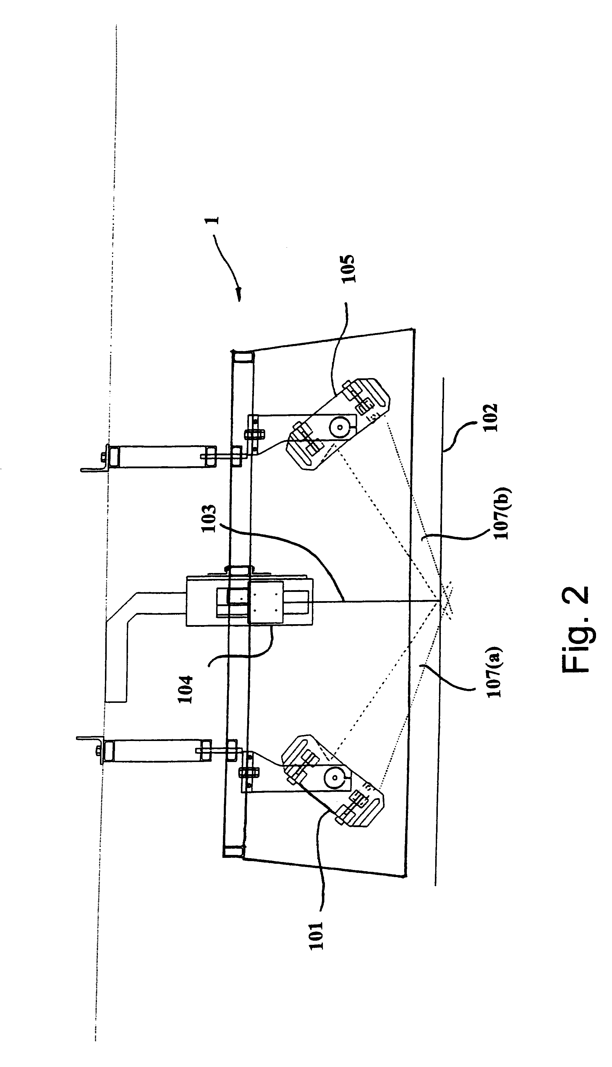
The present invention overcomes the shortcomings of the prior art by providing a crack detection system for accumulating and storage of data relative to the condition of a pavement. The invention further provides a system for obtaining digitized images of a pavement surface and computerized means for automatically analyzing the data thereby enabling efficient monitoring of the condition of the pavement surface. The present invention further provides a lighting assembly for use with a system for monitoring the condition of a road pavement surface wherein the lighting assembly enables illumination of fine pavement detail. The present invention further provides a digital camera for use with a system for monitoring the condition of a road pavement surface wherein the camera includes an automated exposure control enabling incremental snapshots of the pavement surface whilst the camera moves at up to and around 100 km per hour relative to the pavement. The invention further provides pavement monitoring software which stores, compiles and automatically assimilates data in "real time" relating to pavement condition obtained from a digital camera.
There are a number of attendant benefits which attach to the system according to the present invention and these include reduced risk of injury to data collection personnel, less diversion of local resources to manual data collection, reduced time losses, eliminating inconsistencies in manually collected data, confidence in comparisons from year to year and region to region, confidence in accuracy of base data used for planning and budgeting, rational basis for use of cracking data in network performance, reporting and maintenance planning, reduced time at corporate level, collating data for reporting and planning, savings over current manual data collection and savings in cost of maintenance and rehabilitation of road network.

Problems solved by technology

Current methods do not detect cracking of the road network at the stage where early intervention would be cost effective nor attribute the incidence of cracking to a specific location (due to the small sampling).
The existing systems are not capable of providing sufficient crack related data such as the ability to discern cracks on pavement surfaces including chip seal surfaces, at highway speeds.
The existing systems further rely on post processing with manual intervention of image data in the office which often takes days before the data is available.
Thin cracked surfaces are particularly vulnerable in wet weather when traffic pumps water into the road pavement leading to pavement failures which causes a roughening of the surface and decreased asset value of the roads.
Pavements such as roads, carriageways and the like are subject to heavy wear from traffic and degradation from sub-grade movement and deterioration in the pavement material itself.
This is a massive undertaking due to the usually extensive nature of road infrastructure.
Although crack detection can be done visually by skilled personnel, it is almost impossible for visual inspections to obtain the necessary crack data for all sections of road in a particular municipality / region.
The cost to do these inspections is prohibitive due to the amount of labour required and in any event such inspections suffer from the influence of human subjectivity and exposure to traffic hazards.
The images from these cameras are prone to overlap and lack definition.
The current manual methods of crack detection are time consuming and the extent of information gathered is limited.
Manual methods are also capital intensive with poor return.

Method used


Image

  • Road pavement deterioration inspection system
  • Road pavement deterioration inspection system
  • Road pavement deterioration inspection system

Examples


Embodiment Construction

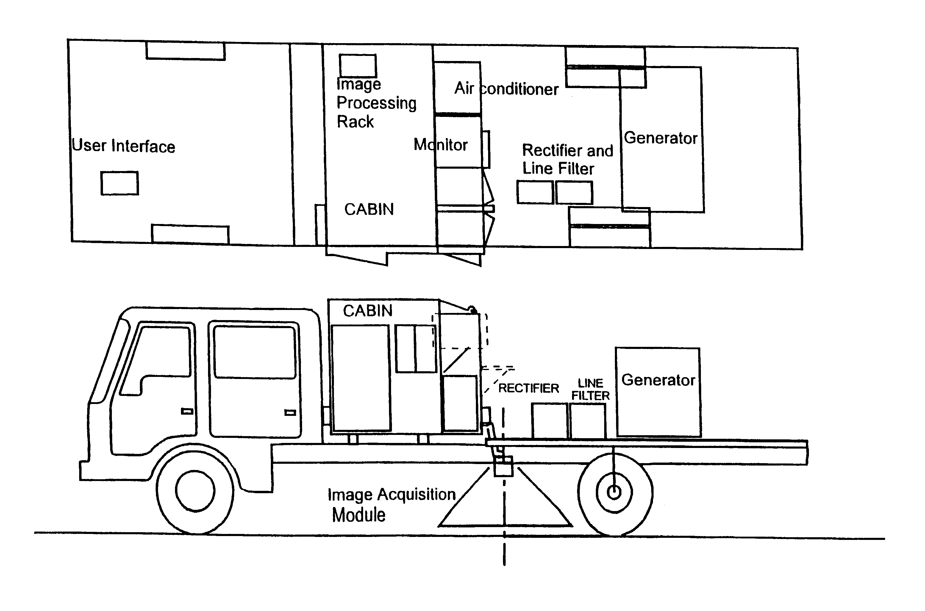
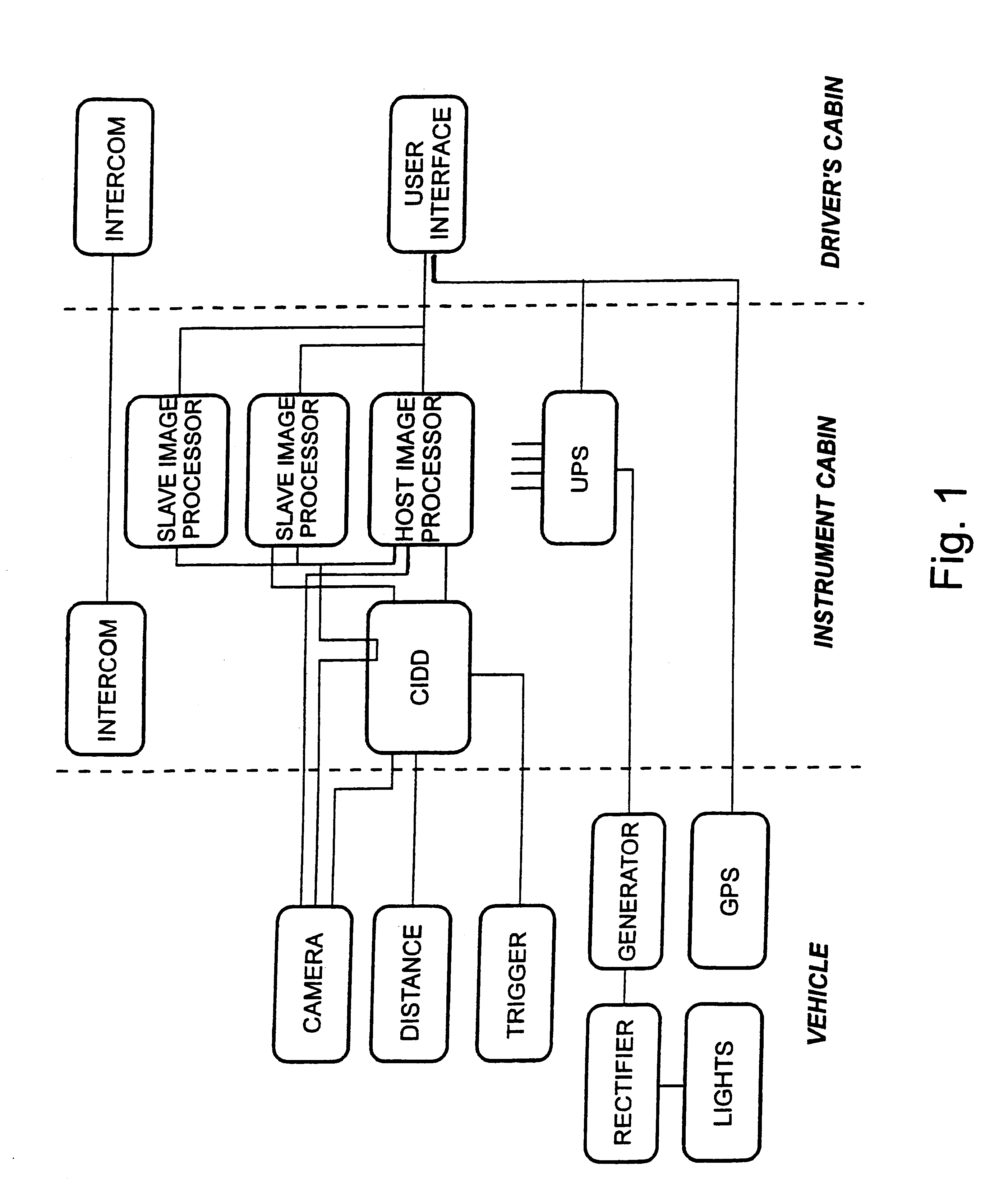
The present invention provides a modular automated system for crack detection in a pavement and more particularly detects finely cracked roads so that early repairs can be made to raise the overall condition of the road network. The automated crack detection system is contained in a vehicle which might be a truck or the like which is configured to enable all integers of the system to be contained within the vehicle. The parameters of the chosen vehicle are determined according to the operating requirements of the system. At the very least, the vehicle must have electrical mains power mainly for illumination, an ability to scan a predetermined width of pavement along with data capture systems to receive and process data captured by the automated crack detection system. Most of the electrical power is required for lighting so that a power generator located on the vehicle will be sized according to the power requirements per module. Other vehicle parameters include specified clearances...


PUM

PropertyMeasurementUnit
speedsaaaaaaaaaa
speedsaaaaaaaaaa
sizeaaaaaaaaaa

Abstract

A system for acquiring, processing, storing, analyzing and reporting data relating to the condition of a road or other pavement surface (102) in real time. The system includes a digital camera (104) mounted on a vehicle and positioned relative to a pavement surface (102) so as to capture images of the pavement surface (102) while the camera (104) is moving relative to the surface (102). The system also includes an illumination assembly (100) to illuminate the region from which an image is taken and an interface between the digital camera (104) and at least one computer. The system also includes a processor in the computer for processing the images to detect and classify cracks and other pavement surface (102) features.

Description

The present invention relates to a road pavement crack detection system and apparatuses associated therewith and more particularly relates to a crack detection system utilizing digital imaging for obtaining and storing data concerning the crack condition of a pavement.Cracking is the visible condition indicator most closely linked to pavement condition. Current methods do not detect cracking of the road network at the stage where early intervention would be cost effective nor attribute the incidence of cracking to a specific location (due to the small sampling). Major cost savings to authorities can be made from early intervention to seal finely cracked roads rather than waiting until the cracks develop to a more serious condition as is the case when using manual methods such as visual inspection. Finely cracked roads for instance can be sealed at a relatively low cost of $2-$4 per square meter on today's values compared to $30-$40 per square meter where cracking has progressed to a...

Claims


Application Information

Patent Timeline
Patent Type & Authority Patents(United States)
IPC IPC(8): G01C7/04G01C7/00G01N21/88
CPCG01C7/04G01N21/88
Inventor FERGUSON, RONALD ALLANPRATT, DAVID NORMANTURTLE, PAUL RICHARDMACINTYRE, IAN BARRYMOORE, DANIEL PETERKEARNEY, PATRICK DALEBEST, MICHAEL JOHNGARDNER, JAMES LAURIEBERMAN, MARKBUCKLEY, MICHAEL JAMESBREEN, JOSEPH EDMONDJONES, RONALD
Owner COMMONWEALTH SCI & IND RES ORG
Learn More