Method and device for operating an internal combustion engine in the event of a fault of a crankshaft sensor

A technology of crankshaft sensor and camshaft sensor, which is applied in the direction of valve device, valve driving device, machine/engine, etc., which can solve the problems such as the deterioration of exhaust characteristics of internal combustion engines, and achieve the effect of reducing exhaust gas

Inactive Publication Date: 2012-11-21
ROBERT BOSCH GMBH
View PDF4 Cites 14 Cited by
  • Summary
  • Abstract
  • Description
  • Claims
  • Application Information

AI Technical Summary

Problems solved by technology

The camshaft can therefore no longer be used to adjust the camshaft for the different operating ranges of the internal combustion engine, thus deteriorating the exhaust characteristics of the internal combustion engine

Method used


Image

  • Method and device for operating an internal combustion engine in the event of a fault of a crankshaft sensor
  • Method and device for operating an internal combustion engine in the event of a fault of a crankshaft sensor
  • Method and device for operating an internal combustion engine in the event of a fault of a crankshaft sensor

Examples


Embodiment Construction

[0019] Like features are marked with like reference numerals.

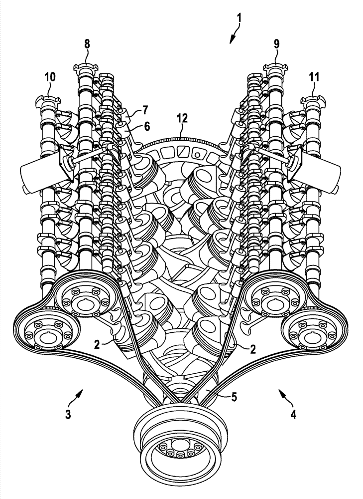
[0020] figure 1 A schematic diagram of a V-shaped internal combustion engine 1 is shown. In this case, cylinders 2 of internal combustion engine 1 are arranged V-shaped in two planes 3 , 4 , wherein crankshaft 5 is positioned at the intersection of these two planes 3 , 4 . Each plane 3, 4 is typically called a bank. Each cylinder 2 is provided with one or more intake valves 6 and exhaust valves 7 . Fresh air and fuel are supplied to the individual cylinders 2 of the internal combustion engine 1 via intake valves 6 , while the combustion products of the cylinders 2 are discharged from the internal combustion engine 1 in the form of exhaust gases via exhaust valves 7 . The intake valve 6 of the first plane 3 of the cylinder 2 is connected to the first camshaft 8 , while the exhaust valve 7 of the first plane 3 is driven by the second camshaft 10 . Similarly, the intake valves of the second plane 4 of the cylinde...


PUM


Abstract

The invention relates to a method for operating an internal combustion engine in the event of a fault of a crankshaft sensor, wherein the internal combustion engine (1) has at least two camshafts (8, 9, 10, 11) and a rotational speed and / or a position of the internal combustion engine (1) is derived from a signal picked off from the camshaft (8, 9, 10, 11). To improve the exhaust-gas behaviour of the internal combustion engine even during a crankshaft emergency running phase, only a first camshaft (11) is used to determine the rotational speed and / or the position of the internal combustion engine (1), whereas the second camshaft (8, 9, 10) is adjusted in terms of its rotational angle in order to realize a variable valve drive at the inlet or outlet valves (6, 7), which are driven by the second camshaft (8, 9, 10), of the internal combustion engine (1).

Description

technical field [0001] The invention relates to a method for operating an internal combustion engine in the event of a crankshaft sensor failure, wherein the internal combustion engine has at least two camshafts, and the speed and / or position of the internal combustion engine is deduced from signals taken from the camshafts, and also relates to a method for carrying out the method installation. Background technique [0002] In today's motor vehicles it is important to precisely determine the rotational speed of the internal combustion engine, since this variable is input to numerous control and regulation processes of the motor vehicle. Usually, this rotational speed is derived from the rotational speed of the crankshaft, which is driven by the mechanical energy generated during the combustion process. The crankshaft is detected here by a crankshaft sensor, which detects the rotational speed and the position of the crankshaft. This signal is provided by a suitable sensor a...

Claims


Application Information

Patent Timeline
Patent Type & Authority Applications(China)
IPC IPC(8): F01L1/34F02D41/22
CPCF01L1/344F01L2820/042F01L2800/12F01L1/34F01L2001/34496F01L2001/0537F01L2820/041F01L2800/11F02D41/222F01L1/04F01L13/00F02D13/00F02D41/22F02D45/00F01L9/20
Inventor U-M.内夫策E.皮奇C.德林格
Owner ROBERT BOSCH GMBH
Why Eureka
Try Eureka