
Plasma display equipment

A plasma display and equipment technology, applied in the direction of alternating current plasma display panels, solid cathode components, cold cathode tubes, etc., can solve problems such as low equipment efficiency, uneven gas exhaust, etc. The effect of the effective distribution area

Inactive Publication Date: 2006-05-17
NANJING LG TONGCHUANG COLOR DISPLAYS SYST CO LTD
View PDF0 Cites 0 Cited by
  • Summary
  • Abstract
  • Description
  • Claims
  • Application Information

AI Technical Summary

Problems solved by technology

However, there are problems such as the exhaust of the necessary gas during the discharge process is not smooth, and the efficiency of the equipment is low.

Method used


Image

  • Plasma display equipment
  • Plasma display equipment
  • Plasma display equipment

Examples


Embodiment Construction

[0027] Hereinafter, the present invention will be described in detail with reference to the accompanying drawings.

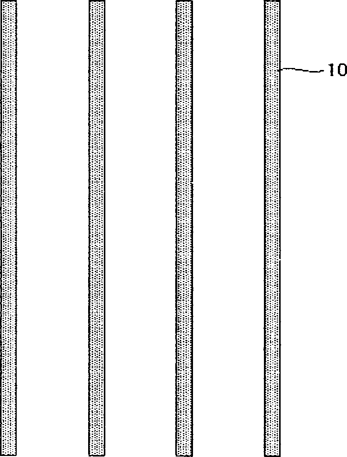
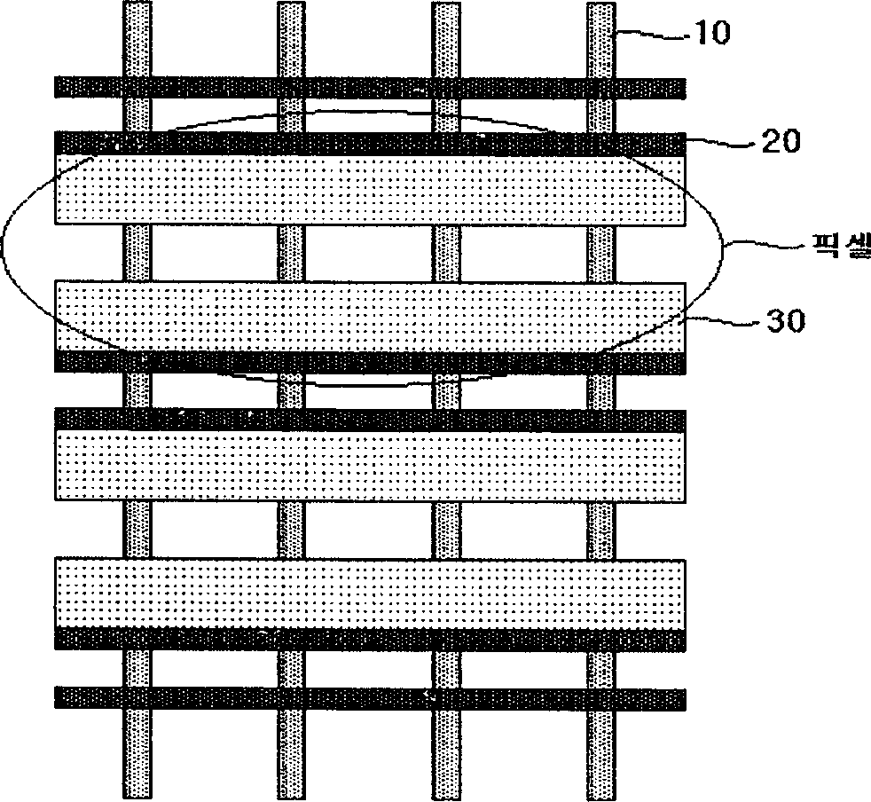
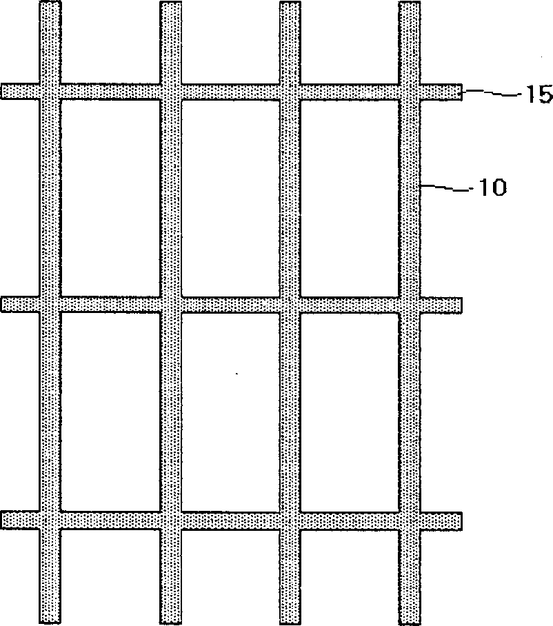
[0028] Figure 5a to Figure 5b is a schematic diagram showing the partition wall structure according to an embodiment of the present invention and the upper plate electrode located on the top of the partition wall. As shown in the figure, the transverse partition wall 45 is provided with a concave-convex curved portion 47 depending on the position of the cell body. The concave-convex curved portion 47 is provided with a concave portion 46 wider than the width of the unit vertical partition wall 40 .

[0029] If this is further described in detail, it means that the horizontal partition wall 45 has a plurality of concave-convex curved parts 47 arranged at intersections with the unit vertical partition wall according to the position of the cell body. One side of the unit vertical partition wall 40 is connected to the protruding portion of the concave-convex curv...


PUM


Abstract

A plasma display unit is prepared as making its horizontal spacing wall be concave ¿C convex structure, setting mating concave ¿C convex structure with air exhaust gap on horizontal spacing wall being used as adjacent cell body set at another side of unit vertical spacing wall for connecting two pieces together, setting topboard bus electrode at top of said horizontal spacing wall not only for avoiding error discharge between cell bodies but also for improving air exhaust property effectively.

Description

【Technical field】 [0001] The present invention relates to plasma display devices. Specifically, the intersecting part of the horizontal partition wall and the firm partition wall in the grid-shaped partition wall structure is provided in a concave-convex shape and well combined. Then, upper board bus electrodes are provided on the upper portions of the horizontal barrier ribs. This can enhance exhaust performance, improve efficiency, increase the effective surface area of ​​the partition wall, and enhance brightness. 【Background technique】 [0002] TFT liquid crystal display devices (LCD), organic EL, FED, etc. are all next-generation display devices. At present, the plasma display (Plsama Display Panel: hereinafter referred to as "PDP") device that is being favored by people is a kind of He+Xe or Ne+Xe gas discharge in the discharge cells isolated by barrier ribs. The 147nm ultraviolet rays generated when irradiating R, G, and B phosphors, and using the luminescence phen...

Claims


Application Information

Patent Timeline
Patent Type & Authority Applications(China)
IPC IPC(8): H01J11/10H01J17/16H01J17/36H01J17/49
Inventor 郑海英
Owner NANJING LG TONGCHUANG COLOR DISPLAYS SYST CO LTD
Learn More