Plasma display panel

a technology of display panel and plasma, which is applied in the direction of electrodes, gas-filled discharge tubes, transportation and packaging, etc., can solve the problems of non-preventable misdischarge, hinder the improvement of luminous efficiency, and may occur in a non-discharge area, so as to prevent misdischarge in a non-discharge region

Inactive Publication Date: 2005-11-17
SAMSUNG SDI CO LTD
View PDF9 Cites 2 Cited by
  • Summary
  • Abstract
  • Description
  • Claims
  • Application Information

AI Technical Summary

Benefits of technology

[0016] A feature in exemplary embodiments of the present invention is to provide a plasma display panel that can prevent misdischarge in a non-discharge region.

Problems solved by technology

However, that hinders improving a luminous efficiency.
Even this structure may not prevent the misdischarge from happening in the direction along the barrier ribs.
Further, in a PDP with partially modified barrier ribs in the structure, misdischarge in a non-discharge area may occur because bus electrodes of the display electrodes placed in the neighboring discharge cells are exposed to the non-discharge area.
Thus, the misdischarge in the non-discharge area may cause the degradation in color purity due to a neon (Ne) light-discharge and in PDP efficiency due to unwanted power consumption.

Method used


Image

  • Plasma display panel
  • Plasma display panel
  • Plasma display panel

Examples


Embodiment Construction

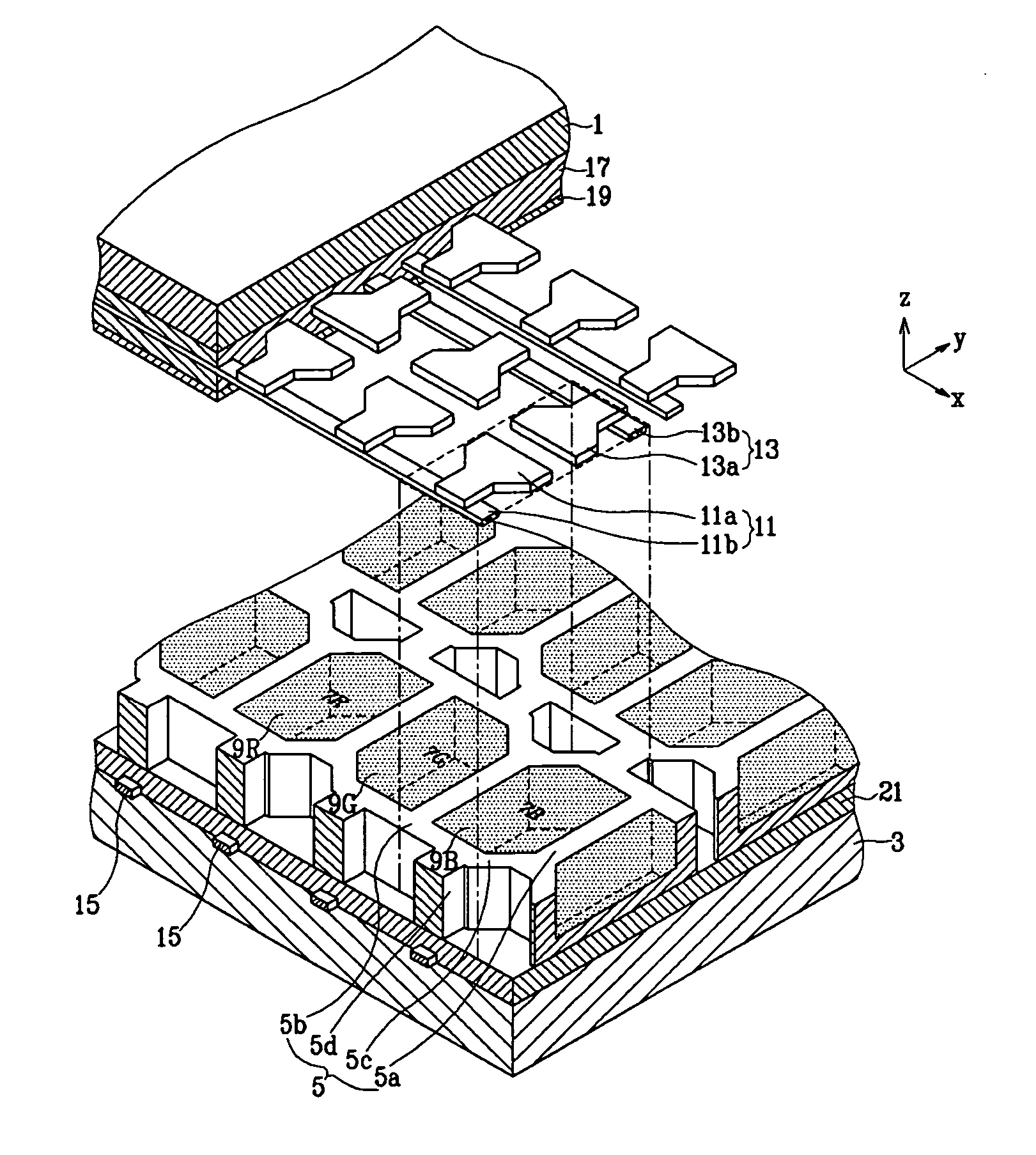
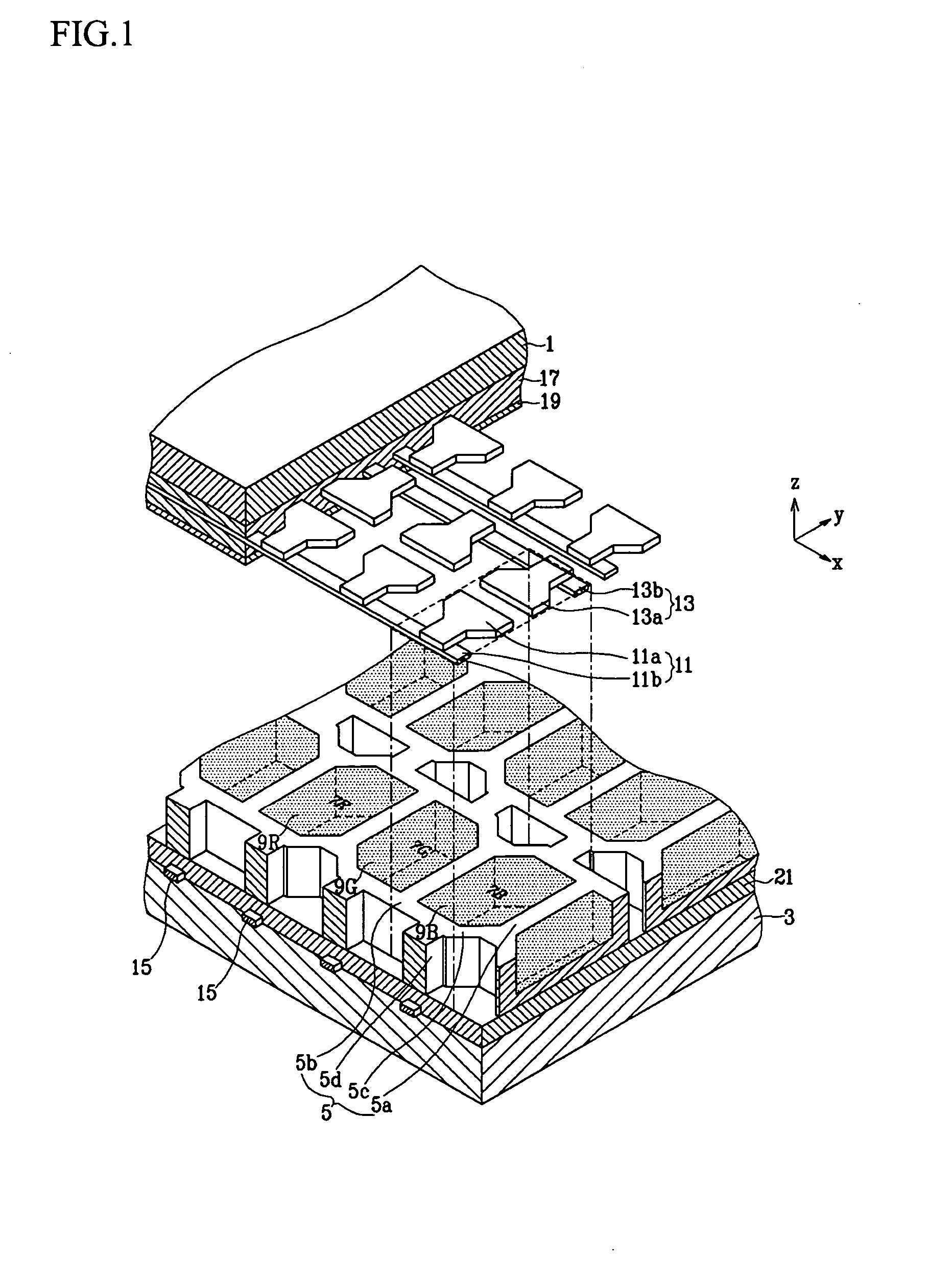
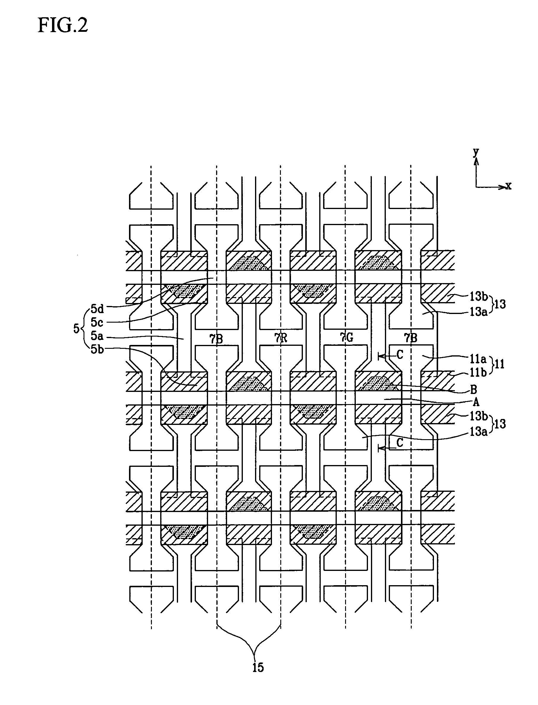
[0036] As shown in FIGS. 1-3, a plasma display panel (PDP) includes a first substrate 1 (front substrate), and a second substrate 3 (rear substrate) facing the first substrate 1. The first and second substrates 1 and 3 are hermetically joined to each other at their respective edges. A plurality of discharge cells 7R, 7G, 7B for plasma discharge are formed by a plurality of barrier ribs 5 positioned between the front substrate 1 and the rear substrate 3. Red (R), green (G) and blue (G) phosphors 9R, 9G, 9B are respectively formed on the inside of the discharge cells 7R, 7G, 7B.

[0037] Corresponding to the discharge cells 7R, 7G, 7B, display electrodes 11, 13 are formed on the first substrate 1, extending in the x-direction and placed parallel to each other with a pitch of the discharge cells 7R, 7G, 7B in the y-direction. Address electrodes 15 are formed on the second substrate 3, extending in the direction (y-direction) crossing the display electrodes 11, 13 and placed parallel to e...


PUM


Abstract

A plasma display panel to prevent misdischarge in a non-discharge region. The plasma display panel includes a first substrate and a second substrate facing the first substrate. A plurality of display electrodes are formed extending on the first substrate, and a plurality of address electrodes are formed extending on the second substrate and cross the display electrodes. Barrier ribs including a plurality of barrier rib members are positioned between the first substrate and the second substrate, and form a plurality of discharge cells and non-discharge regions. A phosphor is formed inside each of the discharge cells. Each of the non-discharge regions includes one of exposure regions where a part of one of the display electrodes is exposed. The exposure regions are placed alternately in an extending direction of the display electrodes.

Description

CROSS REFERENCE TO RELATED APPLICATION [0001] This application claims priority to and the benefit of Korean Patent Application No. 10-2004-0033392, filed on May 12, 2004 in the Korean Intellectual Property Office, the entire content of which is incorporated herein by reference. BACKGROUND OF THE INVENTION [0002] 1. Field of the Invention [0003] The present invention relates to a plasma display panel (PDP) and, in particular, to display electrodes of the PDP. [0004] 2. Description of the Related Art [0005] A plasma display panel (PDP) is generally a display device in which vacuum ultraviolet (VUV) rays from plasma generated by gas discharge excite phosphors to emit red, green, blue visible lights for producing an image. Such a PDP can achieve a large screen display with a size over 60 inches (˜152.4 cm) while keeping its thickness within 10 cm. As an emissive display device like a cathode ray tube, the PDP has features of excellent color reproduction and no distortion along viewing a...

Claims


Application Information

Patent Timeline
Patent Type & Authority Applications(United States)
IPC IPC(8): H01J11/12H01J11/16H01J11/22H01J11/24H01J11/26H01J11/32H01J11/34H01J11/36
CPCH01J11/12H01J11/24H01J2211/365H01J2211/245H01J11/36B60J3/0278B60R11/0211B60R11/0229B60R2011/0035
Inventor KWON, JAE-IKKANG, KYOUNG-DOO
Owner SAMSUNG SDI CO LTD
Why Eureka
Try Eureka