Plasma display device and its driving method

A technology of a display device and a driving method, which is applied to identification devices, static indicators, instruments, etc., can solve problems such as mis-discharge of scanning electrodes, and achieve the effects of preventing mis-discharge of addressing, preventing mis-discharge at high temperature, and stably driving

Inactive Publication Date: 2007-08-29
NANJING LG TONGCHUANG COLOR DISPLAYS SYST CO LTD
View PDF0 Cites 2 Cited by
  • Summary
  • Abstract
  • Description
  • Claims
  • Application Information

AI Technical Summary

Problems solved by technology

[0022] As above, the data pulse applied to the addressing electrode X affects the wall charge formed on the above-mentioned scanning electrode Y, and the higher the temperature of the plasma display panel, the more serious the impact, mainly in the scanning electrode located at the lower end of the plasma display panel. Misdischarge phenomenon occurs

Method used


Image

  • Plasma display device and its driving method
  • Plasma display device and its driving method
  • Plasma display device and its driving method

Examples


Embodiment Construction

[0048] Hereinafter, embodiments of the present invention are introduced with reference to the attached figures.

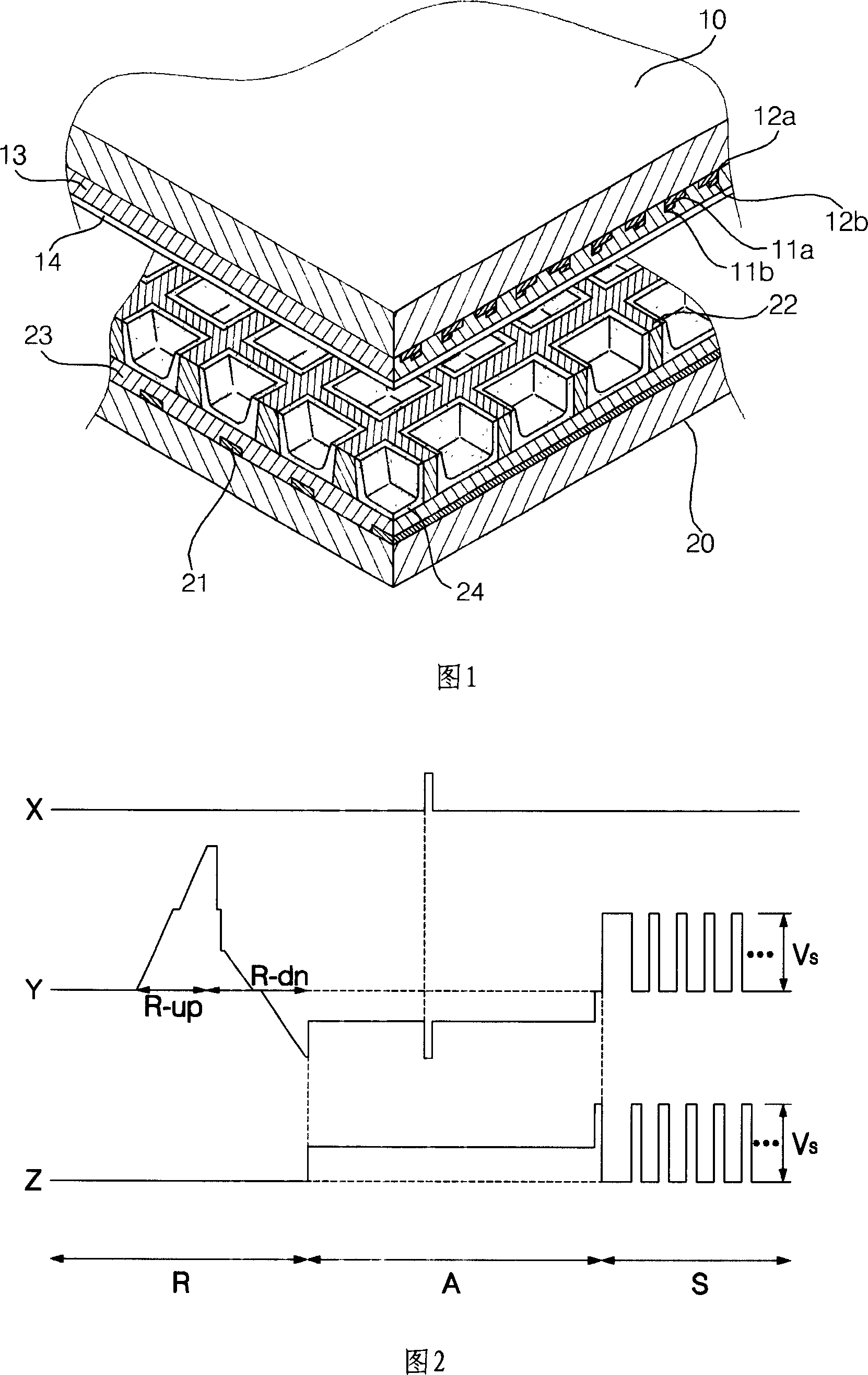
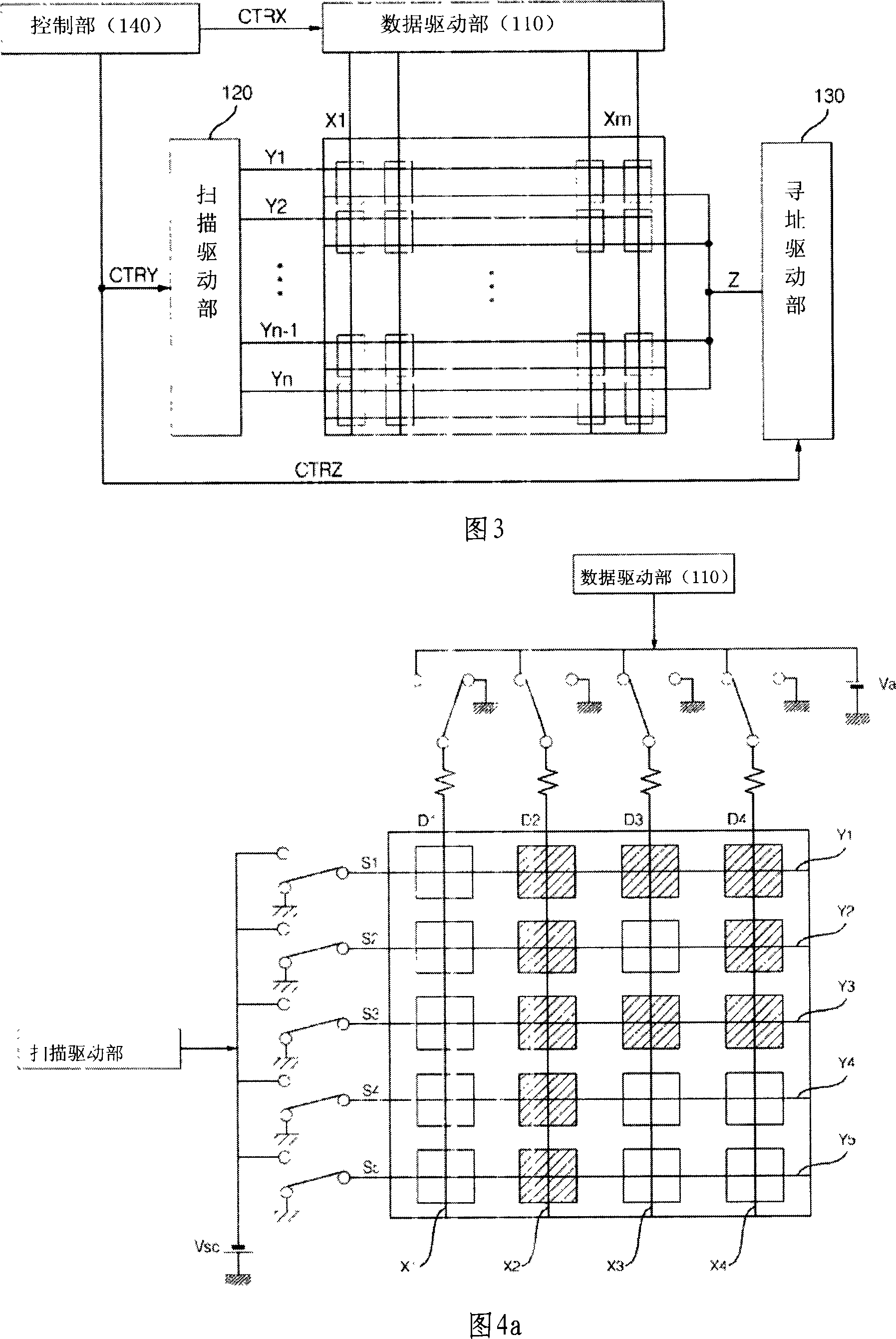
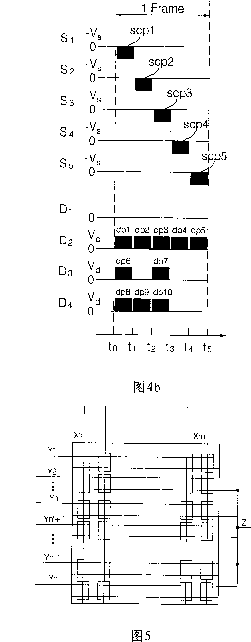
[0049]As shown in FIG. 3 , the plasma display panel includes: a plurality of address electrodes X arranged in a column direction and a plurality of scan electrodes Y and sustain electrodes Z arranged in a row direction. The scan electrodes are formed corresponding to the sustain electrodes, and one ends of the sustain electrodes are connected to each other to apply the same voltage.

[0050] The plasma display panel is composed of a front substrate on which the scan electrodes Y and sustain electrodes Z are horizontally alternately formed and a rear substrate on which the address electrodes X are formed. The discharge spaces are arranged to face each other with the discharge spaces interposed therebetween, and the discharge spaces located at the intersections of the scan electrodes and the sustain electrodes and the address electrodes form basically one discharge s...


PUM


Abstract

A plasma display device and a driving method thereof are provided to prevent a high-temperature error in discharge by varying a scan voltage applied to a scan electrode, according to temperature. A plasma display device includes a scan driver(120) having plural switches(S1~S5). The switches apply scan pulses on respective scan electrodes(Y1~Y5). When an address period begins, a scan pulse is sequentially applied on the scan electrodes irrespective of an image signal. The first scan switch is turned on and a negative voltage is applied on the first scan electrode, so that the scan pulse is applied on the first scan electrode. The rest scan switches are sequentially turned on, so that the scan pulses are applied on the scan electrodes. At the application timing of the scan pulse, a positive data pulse is applied on an address electrode, so that an address discharge is generated between scan and address electrodes. The address electrode is formed to cross the scan electrode.

Description

technical field [0001] The present invention is an invention related to a plasma display device and a driving method thereof, and particularly an invention related to a plasma display device and a driving method thereof capable of preventing high-temperature misdischarge by changing an applied scanning electrode according to temperature. Background technique [0002] The plasma display panel is a display device that discharges the gas inside the substrate, and the generated vacuum ultraviolet rays (VUV) collide with phosphors inside the substrate to generate light. As shown in Fig. 1, a plasma display panel is largely composed of a front substrate (A) and a rear substrate (B). [0003] The front substrate (A) is composed of scan electrodes (1) and sustain electrodes (2) formed in sequence, and a dielectric protection layer (4) laminated on the scan electrodes and sustain electrodes. [0004] The scan electrodes (1) and the sustain electrodes (2) respectively have a relative...

Claims


Application Information

Patent Timeline
Patent Type & Authority Applications(China)
IPC IPC(8): G09G3/28G09G3/20H01J17/49G09F9/313G09G3/293G09G3/296
CPCG09G3/293G09G3/296
Inventor 金垣淳鄭景振崔允暢都鉉洛
Owner NANJING LG TONGCHUANG COLOR DISPLAYS SYST CO LTD
Why Eureka
Try Eureka