
Collapsible shoe rack

a shoe rack and collapsible technology, applied in the field of shoe racks, can solve the problems of occupying a lot of space in the rack, affecting the storage of taller items such as boots, and -folding racks, and achieve the effect of convenient storage and efficient transportation

Active Publication Date: 2017-08-31
IP POWER HLDG
View PDF1 Cites 2 Cited by
  • Summary
  • Abstract
  • Description
  • Claims
  • Application Information

AI Technical Summary

Benefits of technology

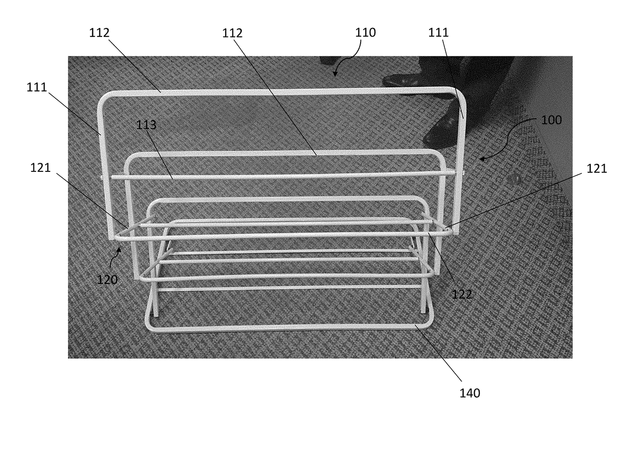
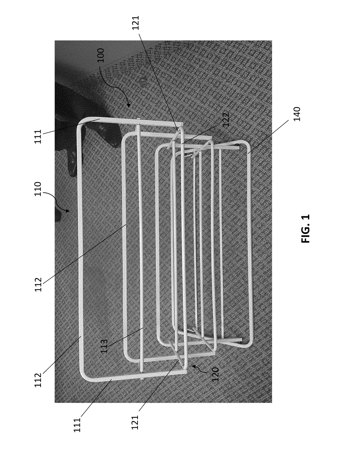
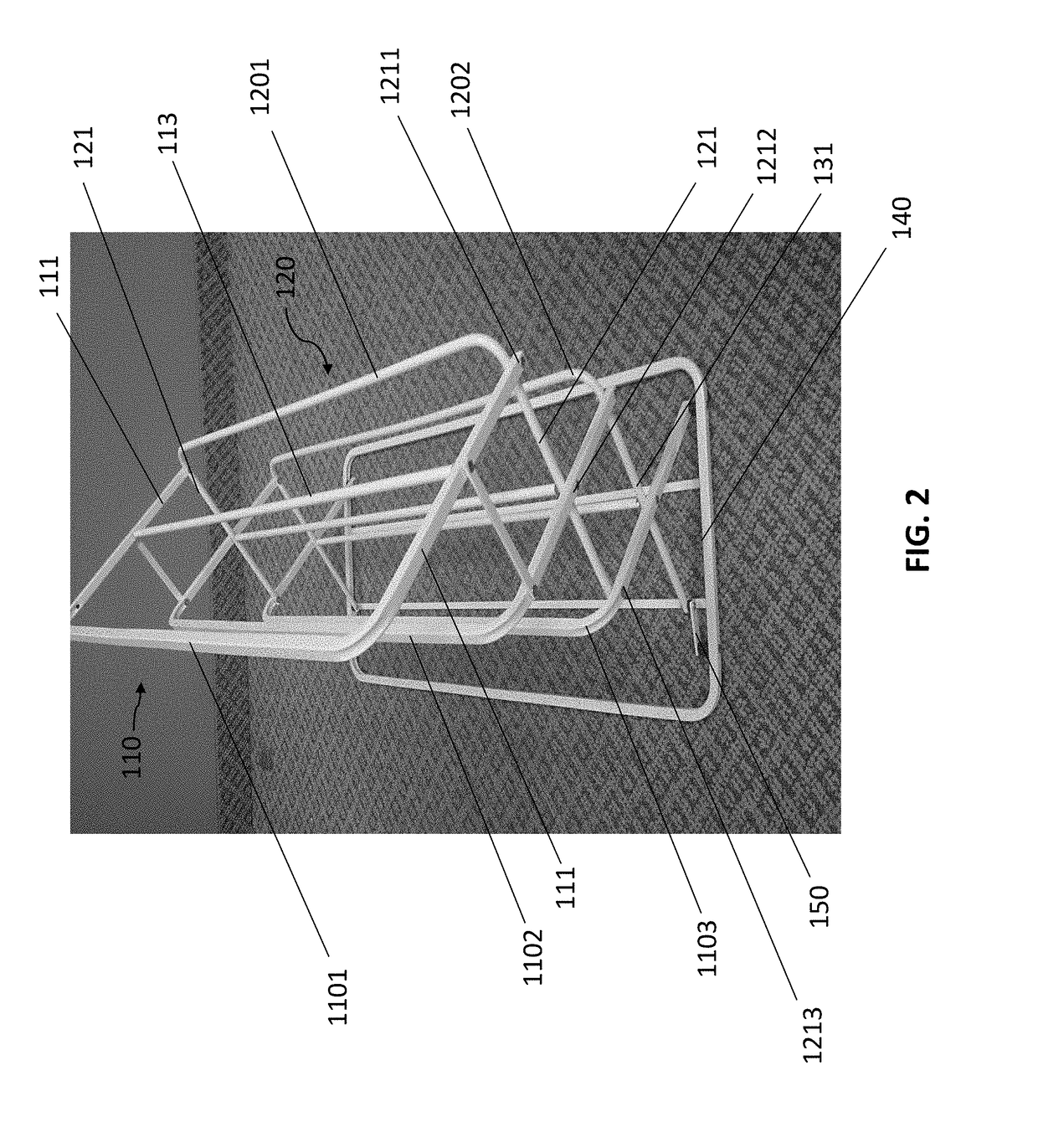
This invention is a collapsible shoe rack that can be easily stored, transported, extended, and collapsed on the ground quickly. It consists of a plurality of shoe retaining members, connecting members, and a base. The shoe retaining members are arranged in a reverse U-shaped manner and connected with the connecting member on each side arm. The connecting member is also a U-shaped unit with two parallel connecting arms. When the shoe rack is collapsed, the size of the shoe rack can be significantly reduced because the shoe retaining members and connecting members can all be stacked up to minimize the occupied space. Overall, this invention provides a more convenient, efficient, and compact shoe rack design.

Problems solved by technology

Numerous shoe rack designs have been presented, however, many conventional racks have arms that project outwards but do not fold up, requiring the rack to take up a lot of space even when not in use or when in transport.
In addition, the crossbars of non-folding racks can interfere with the storage of taller items such as boots.
Even though the shoe rack in the '406 patent is foldable, the folded shoe rack is still bulky and takes a substantial size of the space, which is not easy to store or transport the shoe rack, even after it is folded.
However, like the foldable shoe rack in the '406 patent, the reconfigurable rack in the '156 patent still takes a lot of spaces to store or transport, even though the size of which is reconfigurable.

Method used


Image

  • Collapsible shoe rack
  • Collapsible shoe rack
  • Collapsible shoe rack

Examples


Embodiment Construction

[0021]The detailed description set forth below is intended as a description of the presently exemplary device provided in accordance with aspects of the present invention and is not intended to represent the only forms in which the present invention may be prepared or utilized. It is to be understood, rather, that the same or equivalent functions and components may be accomplished by different embodiments that are also intended to be encompassed within the spirit and scope of the invention.

[0022]Unless defined otherwise, all technical and scientific terms used herein have the same meaning as commonly understood to one of ordinary skill in the art to which this invention belongs. Although any methods, devices and materials similar or equivalent to those described can be used in the practice or testing of the invention, the exemplary methods, devices and materials are now described.

[0023]All publications mentioned are incorporated by reference for the purpose of describing and disclos...


PUM


Abstract

A collapsible shoe rack may include a plurality of shoe retaining members with two parallel side arms integrated with a horizontal arm as a single piece, and a plurality of connecting members with two parallel side arms and a horizontal arm. In one embodiment, the shoe retaining members are arranged in a reverse U-shaped manner in the shoe rack, and each of the shoe retaining members is connected with the connecting member. A locking member is disposed at the base of the shoe rack and pivotally connected to the base at one end, and the connecting member at the other end. The locking unit is configured to lock the entire structure of shoe rack to prevent it from collapsing

Description

CROSS-REFERENCE TO RELATED APPLICATIONS[0001]This application claims priority under 35 U.S.C. §119 (e) to U.S. Provisional Patent Application Ser. No. 62 / 300,011, filed on Feb. 25, 2016, the entire contents of which are hereby incorporated by reference.FIELD OF THE INVENTION[0002]The present invention is directed to a shoe rack, and in particular to a collapsible shoe rack, the size of which can be easily and significantly minimized when not in use.BACKGROUND OF THE INVENTION[0003]It is generally known to attach various article holding devices, such as shoe racks, over a top edge of a household door to gain additional storage spaces. Door-mounted shoe racks are popular items since they represent a relatively simple way to create additional space in a closet or other room. Numerous shoe rack designs have been presented, however, many conventional racks have arms that project outwards but do not fold up, requiring the rack to take up a lot of space even when not in use or when in tran...

Claims


Application Information

Patent Timeline
Patent Type & Authority Applications(United States)
IPC IPC(8): A47B61/04A47B43/00
CPCA47B43/00A47B61/04
Inventor ZHU, SHOU QIANG
Owner IP POWER HLDG
Learn More