Eureka AIR delivers breakthrough ideas for toughest innovation challenges, trusted by R&D personnel around the world.

Image forming apparatus, image forming system, and notification method

Active Publication Date: 2017-11-02
KONICA MINOLTA INC
View PDF5 Cites 3 Cited by
  • Summary
  • Abstract
  • Description
  • Claims
  • Application Information

AI Technical Summary

Benefits of technology

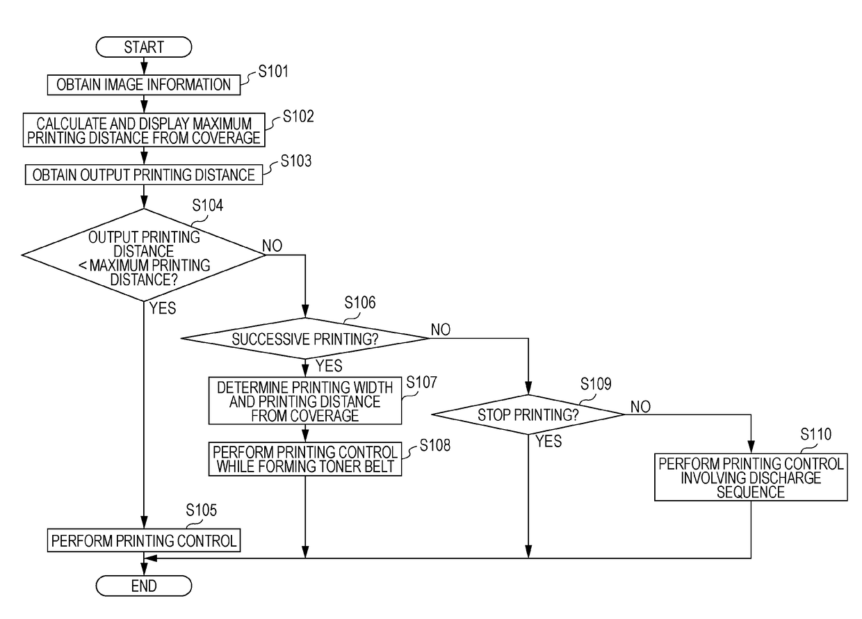
The present invention aims to provide an image forming apparatus, system, and notification method that can reduce the wasteful consumption of long paper sheets during printing.

Problems solved by technology

However, in the case of an image forming apparatus that performs image formation on a continuous paper sheet, a region large enough to form a toner belt cannot be provided between regions where images are formed, and thus degraded toner cannot be discharged from the developing device as the image forming apparatus for a cut paper sheet does.
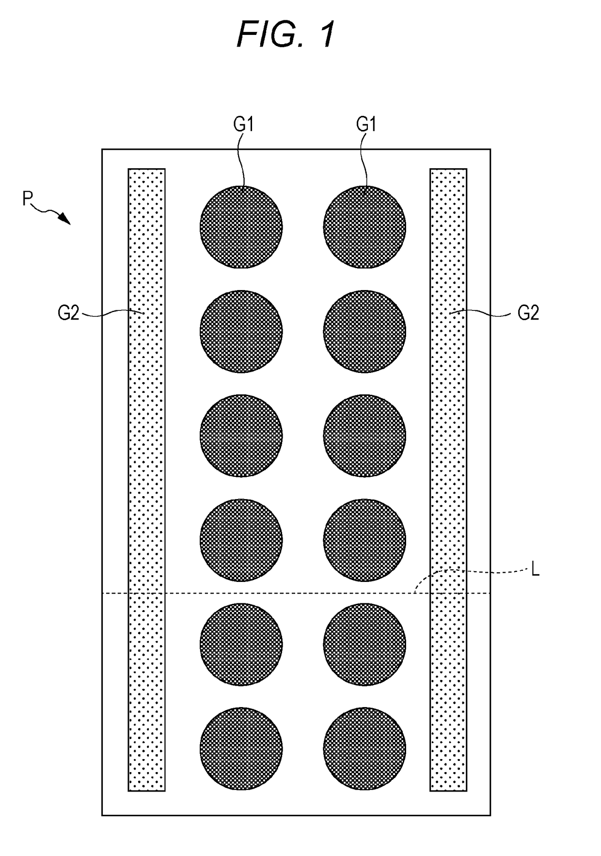
However, the technique described in JP 5741656 B has a problem that, in the case where the coverage is equal to or larger than the threshold value, the toner belts G2 are discharged onto the long paper sheet P even if the ratio of degraded toner in the developing device is relatively small, and thus a region for printing becomes smaller and the long paper sheet P is consumed wastefully.

Method used


Image

  • Image forming apparatus, image forming system, and notification method
  • Image forming apparatus, image forming system, and notification method
  • Image forming apparatus, image forming system, and notification method

Examples


Embodiment Construction

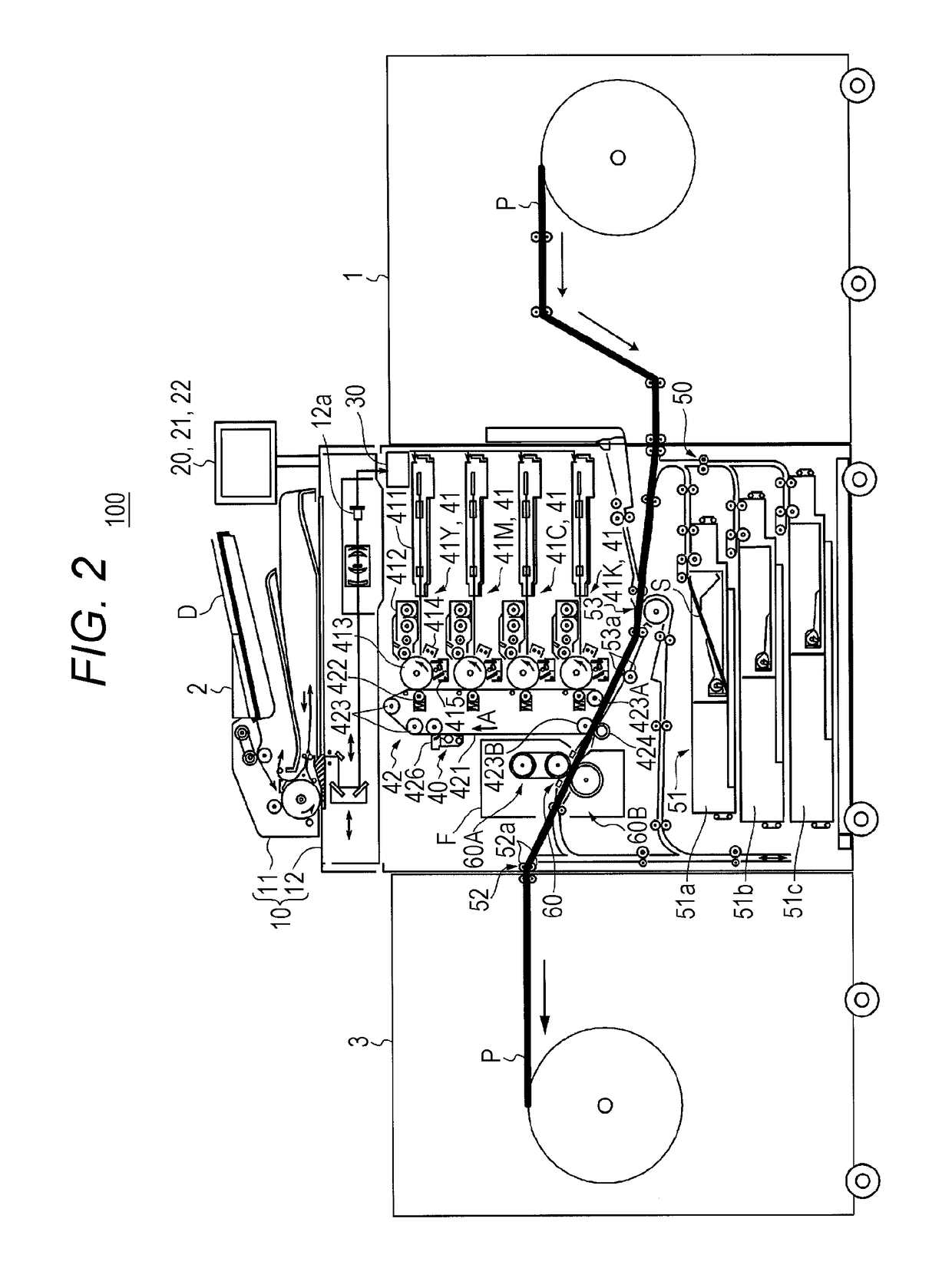
[0028]Hereinafter, an embodiment of the present invention will be described in detail with reference to the drawings. However, the scope of the invention is not limited to the illustrated examples. FIG. 2 schematically illustrates an overall configuration of an image forming system 100 according to the present embodiment. FIG. 3 illustrates a main part of a control system of the image forming apparatus 2 provided for the image forming system 100 according to the present embodiment.

[0029]The image forming system 100 is a system that uses a long paper sheet P illustrated by a thick line in FIG. 2 or a paper sheet S (not a long paper sheet) as a recording medium and forms an image on the long paper sheet P or the paper sheet S.

[0030]The long paper sheet P is a long paper sheet that has a length, for example, exceeding the width of the body of the image forming apparatus 2 in a conveyance direction thereof, and examples thereof include roll paper sheets and continuous paper sheets.

[0031...


PUM


Abstract

An image forming apparatus includes: an image forming portion that includes a developing portion configured to supply toner to an image bearing member bearing an electrostatic latent image formed thereon to develop the electrostatic latent image as a toner image, and is configured to form a toner image on a long paper sheet; a notification portion configured to notify a user about information; and a control portion configured to calculate, in accordance with coverage of a toner image that is a target of image formation, a toner image formation distance with which successive image formation is possible without forcibly discharging degraded toner from the developing portion, and to control the notification portion to notify the calculated toner image formation distance as a first toner image formation distance.

Description

[0001]The entire disclosure of Japanese Patent Application No. 2016-091520 filed on Apr. 28, 2016 including description, claims, drawings, and abstract are incorporated herein by reference in its entirety.BACKGROUND OF THE INVENTIONField of the Invention[0002]The present invention relates to an image forming apparatus, an image forming system, and a notification method.Description of the Related Art[0003]Generally, an image forming apparatus (for example, a printer, a copier, and a facsimile machine) utilizing an electrophotographic process technique forms an electrostatic latent image by irradiating (exposing) an electrified photosensitive drum (image bearing member) with laser light based on image data. Then, the image forming apparatus visualizes the electrostatic latent image as a toner image by supplying toner from a developing device to the photosensitive drum bearing the electrostatic latent image formed thereon. Further, the image forming apparatus forms the toner image on a...

Claims


Application Information

Patent Timeline
IPC IPC(8): G03G15/00
CPCG03G15/5016G03G15/0844G03G15/556G03G15/652G03G2215/00029G03G2215/00033G03G2215/00037G03G2215/0005G03G2215/00755
Inventor TOMINO, TOSHIAKI
Owner KONICA MINOLTA INC
Why Eureka
Eureka Blog
Learn More