
Gate assembly employing a dual actuator latching mechanism

a latching mechanism and gate technology, applied in the field of safety gates, can solve the problems of not being designed, wagnitz does not teach or disclose, and significant dexterity

Active Publication Date: 2017-12-07
PROOFED INC
View PDF20 Cites 21 Cited by
  • Summary
  • Abstract
  • Description
  • Claims
  • Application Information

AI Technical Summary

Benefits of technology

The present invention provides a safety gate apparatus that can be unlatched and unlocked manually or remotely using a pivoting lever and matching pawls. The apparatus includes a locking block and a driving mechanism in communication with the pawls to shift the lever between the pawls to lock or unlock the gate. The apparatus also includes a remote actuator in wireless communication with the driving mechanism to unlock the gate. A biasing element or a spring element can be used to position the lever in the locked or unlocked position. The apparatus can be supported by a frame assembly and can also include active electronics for sensing and processing the gate's position. Overall, the invention provides a safety gate that is simpler yet more versatile and efficient for both manual and remote unlatching.

Problems solved by technology

Known latching mechanisms are unlatched manually or remotely and are actuated in either a complicated way, or in a way that requires significant dexterity and / or strength to unlatch the mechanisms.
Known safely gates are not designed to actuate a latching mechanism both manually and remotely with a simple yet unique locking lever and pawl mechanism.
Additionally, known latching mechanisms do not automatically re-lock after a user has passed through subsequent to manual and remote unlatching.
Wagnitz does not teach or disclose a latching mechanism with any manually unlatching elements nor does Wagnitz teach or disclose a locking lever and matching pawls mechanism.
Significantly, known safety gates do not teach or disclose a gate assembly employing a dual actuator latching mechanism for remote and manual latch release and automatic relocking having a simple yet unique locking lever and pawl mechanism.

Method used


Image

  • Gate assembly employing a dual actuator latching mechanism
  • Gate assembly employing a dual actuator latching mechanism
  • Gate assembly employing a dual actuator latching mechanism

Examples


Embodiment Construction

[0030]The following description is provided to enable those skilled in the art to make and use the described embodiments set forth in the best modes contemplated for carrying out the invention. Various modifications, however, will remain readily apparent to those skilled in the art. Any and all such modifications, equivalents, and alternatives are intended to fall within the spirit and scope of the present invention.

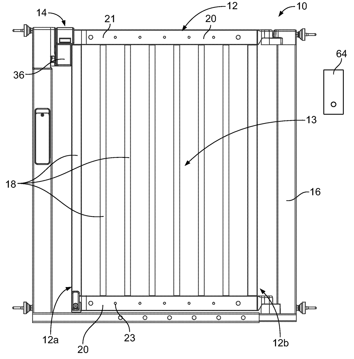
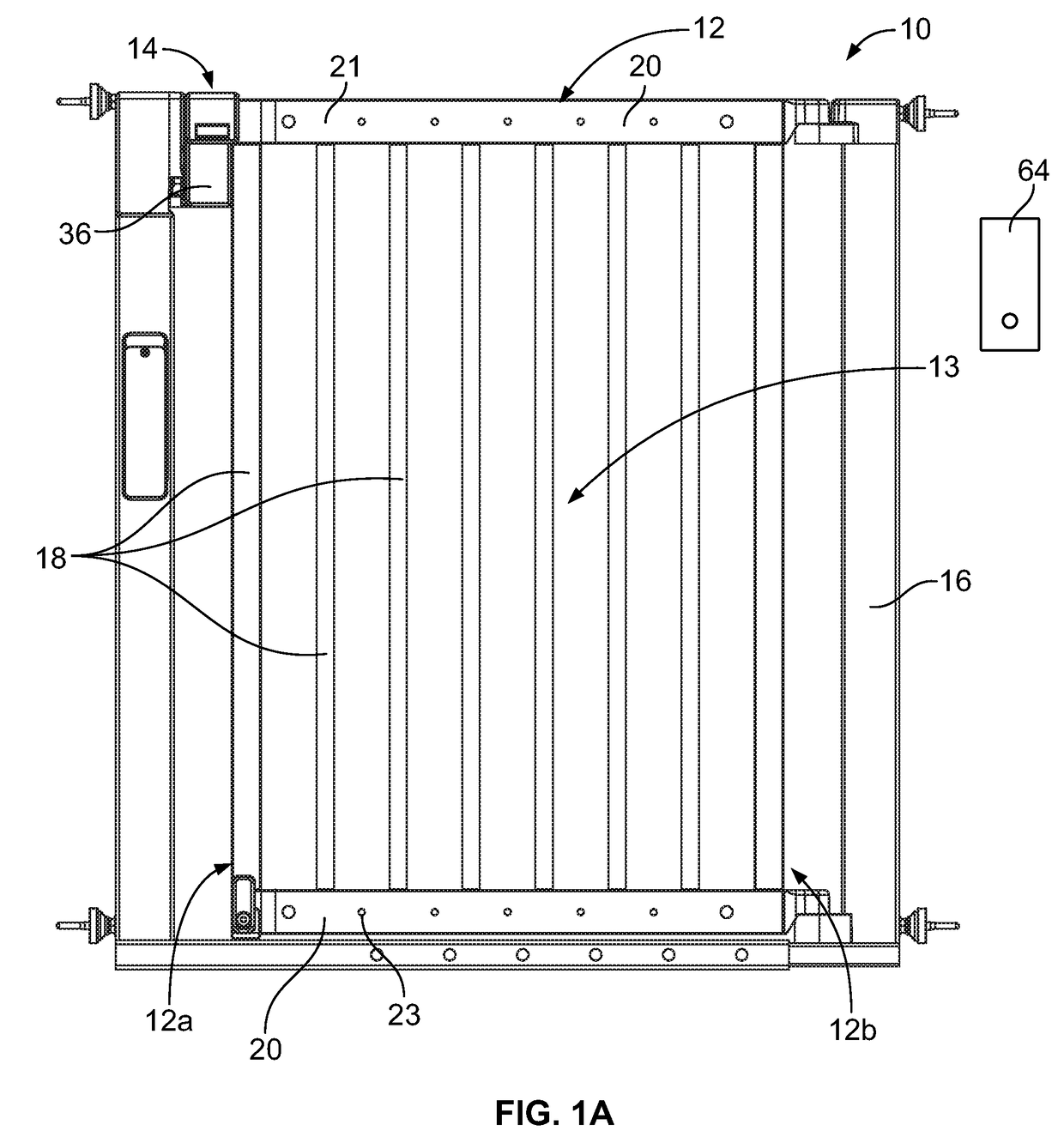
[0031]A gate assembly 10, as seen in FIG. 1A, is generally seen to include a pivoting gate element 12 secured to a doorway and / or passageway and employing a dual actuator latching mechanism 14 for simple yet unique remote and manual latch release, freeing the gate to swing to an open position, and automatic re-lock when the gate swings back to the closed position. In the present described embodiment, the gate assembly most reliably re-locks automatically if the gate is first swung open to 45 degrees or more before the gate is slammed closed. Additionally, the gate assemb...


PUM


Abstract

A gate assembly including a pivoting gate element secured to a doorway and / or passageway and employing a dual actuator latching mechanism having a simple yet unique locking lever and pawl mechanism for remote and manual latch release freeing the gate to swing to an open position, and automatic re-locking of the latching mechanism. The gate assembly includes a frame element for supporting the pivoting gate element and securing the gate to a doorway and / or passageway as well as latching the gate to a closed position at the frame element.

Description

PRIORITY CROSS-REFERENCE TO RELATED APPLICATION[0001]This application claims priority pursuant to 35 U.S.C. 119(e) from U.S. Provisional Patent Application No. 62 / 346,057, filed on Jun. 6, 2016.BACKGROUND OF THE INVENTION1. Field of the Invention[0002]The present invention relates to safety gates and more particularly to a gate assembly employing a dual actuator latching mechanism for remote and manual latch release and automatic re-locking having a simple yet unique locking lever and pawl mechanism.2. Background of the Invention[0003]Safety and / or security gates secured to a doorway and / or passageway for preventing young children and pets from passing through are known and seen to include various mechanisms for latching and unlatching a gate element. Most safety gates include a frame assembly for securing the gate to a doorway or passageway opening either frictionally, employing a tension mechanism, or more permanently, by mounting the frame on the doorway / passageway with hardware ...

Claims


Application Information

Patent Timeline
IPC IPC(8): E05B65/00E06B11/04E05C3/16E05B47/00E06B9/00
CPCE05B65/0007E05B65/0014E05B47/0012E05B47/0046E06B2009/002E06B9/00E06B11/04E05B2047/0023E05B2047/0068E05C3/16E05B47/0603
Inventor SCHORT, AMANDAHAMLIN, CHRISTOPHERCARRASCA, ROBERTWOJCIK, JAMES JOHN
Owner PROOFED INC
Learn More