Hydrodynamic Plain Bearing and Exhaust-Gas-Driven Turbocharger

a technology of exhaust gas and turbocharger, which is applied in the direction of sliding contact bearings, mechanical equipment, machines/engines, etc., can solve the problems of high design and production costs, and cannot be designed, however, for continuous high sliding speeds, and achieve the effect of reducing frictional energy in the contour segmen

Active Publication Date: 2018-03-15
BOSCH MAHLE TURBO SYST GMBH & CO KG
View PDF0 Cites 5 Cited by
  • Summary
  • Abstract
  • Description
  • Claims
  • Application Information

AI Technical Summary

Benefits of technology

[0015]The object of the invention is to furnish a hydrodynamic plain bearing and an exhaust-gas-driven turbocharger having a hydrodynamic plain bearing, improved utilization properties being achieved.
[0018]A decrease in coefficients of friction is achieved by the sectorization of the bearing system both in the region of the contour segments and, in particular, in the region of the transition segment. In addition, bearing pressure transfer from the radial bearing region to the axial bearing region is improved with this bearing. Because a continuous transition between the individual contour segments that are responsible for axial and radial load capacity can be created with the transition segment, an increase in load capacity for the same frictional energy, or alternatively a decrease in frictional energy, can be achieved. The occurrence of instabilities in the form of half-frequency oil whirls is actively reduced by the sectorization of the bearing arrangement. This results in less noise emission from the hydrodynamic plain bearing, and internal and external bearing loads are furthermore considerably decreased thereby. The plain bearing according to the present invention also produces an elevated pumping effect, which results in a decrease in oil pressure requirement.
[0019]According to a preferred embodiment of the invention, provision is made that at least some of the lubrication wedges of the contour segments and of the transition segment are led into one another so as to result in a continuously differentiable contour profile in an axial bearing direction. A continuous, uninterrupted load capacity over the contour segments and the transition segment is thereby achieved.
[0020]One conceivable inventive alternative is such that the contour segments that are led into one another in an axial bearing direction, and the at least one contour segment, each form sectors; and that the sectors of those contour segments and of the at least one transition segment form a bearing sector. It is thereby possible to construct a hydrodynamic plain bearing having several bearing sectors that are arranged with a distribution in a circumferential direction. The bearing sectors can preferably be arranged symmetrically with respect to one another. Each bearing sector serves for the transfer of both radial and axial forces. It is thereby possible to implement plain bearings with which large loads can be transferred in a very small physical space.
[0028]According to a further variant of the invention, provision can be made that the ratio of the maximum contour depth of a sector in the contour segment to the nominal height of the bearing clearance in the contour segment is selected to be in the range between 0.5≦(tmax / c)≦6. An optimum compromise in terms of load capacity and reduction of frictional energy in the contour segment is thereby achieved.

Problems solved by technology

The two bearing types must then each be calculated and designed separately from one another, resulting in correspondingly high costs for both design and production.
These are not designed, however, for continuously high sliding speeds due to rotation of the counter-element (rotor) around its axis.

Method used


Image

  • Hydrodynamic Plain Bearing and Exhaust-Gas-Driven Turbocharger
  • Hydrodynamic Plain Bearing and Exhaust-Gas-Driven Turbocharger
  • Hydrodynamic Plain Bearing and Exhaust-Gas-Driven Turbocharger

Examples


Embodiment Construction

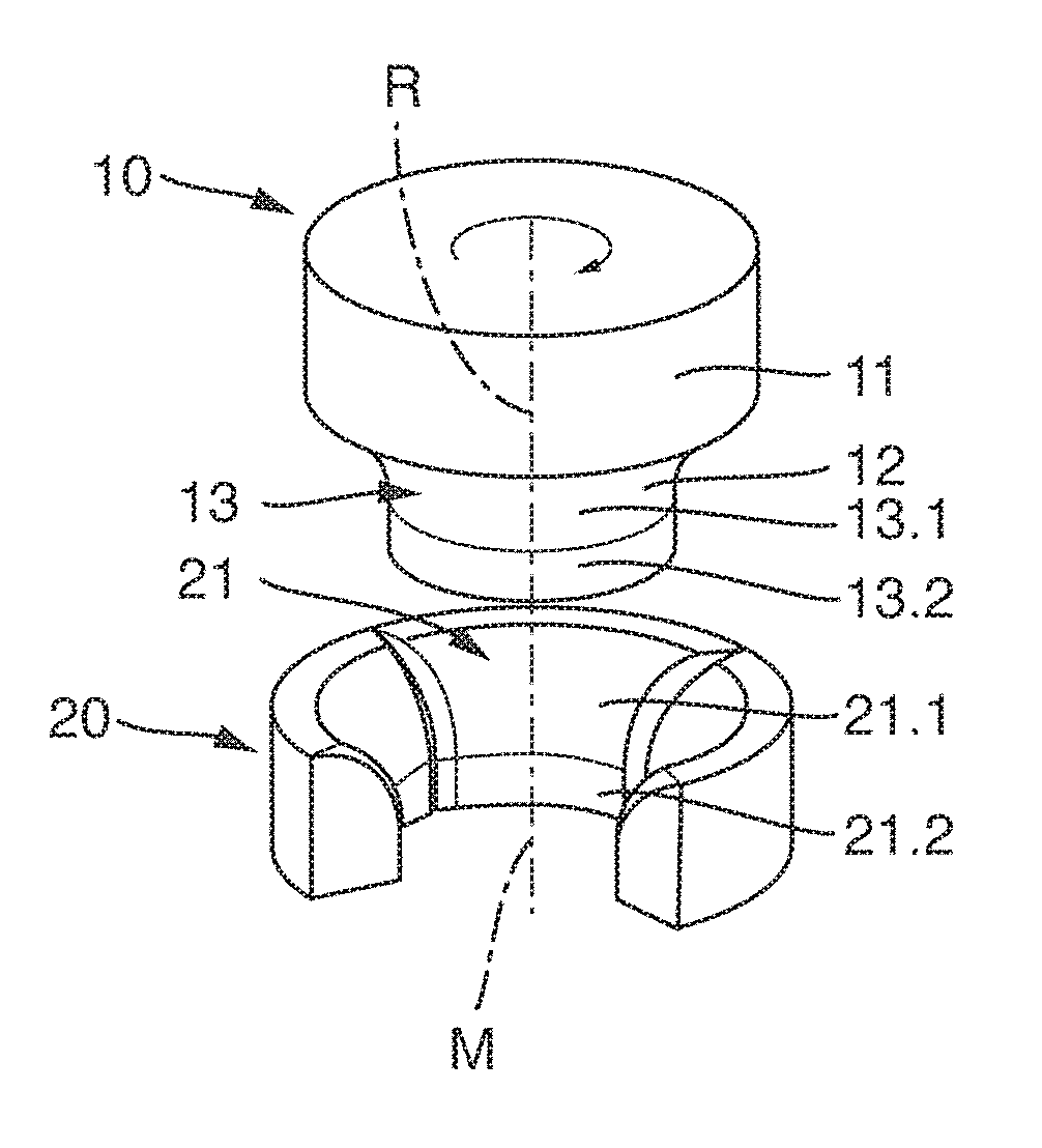
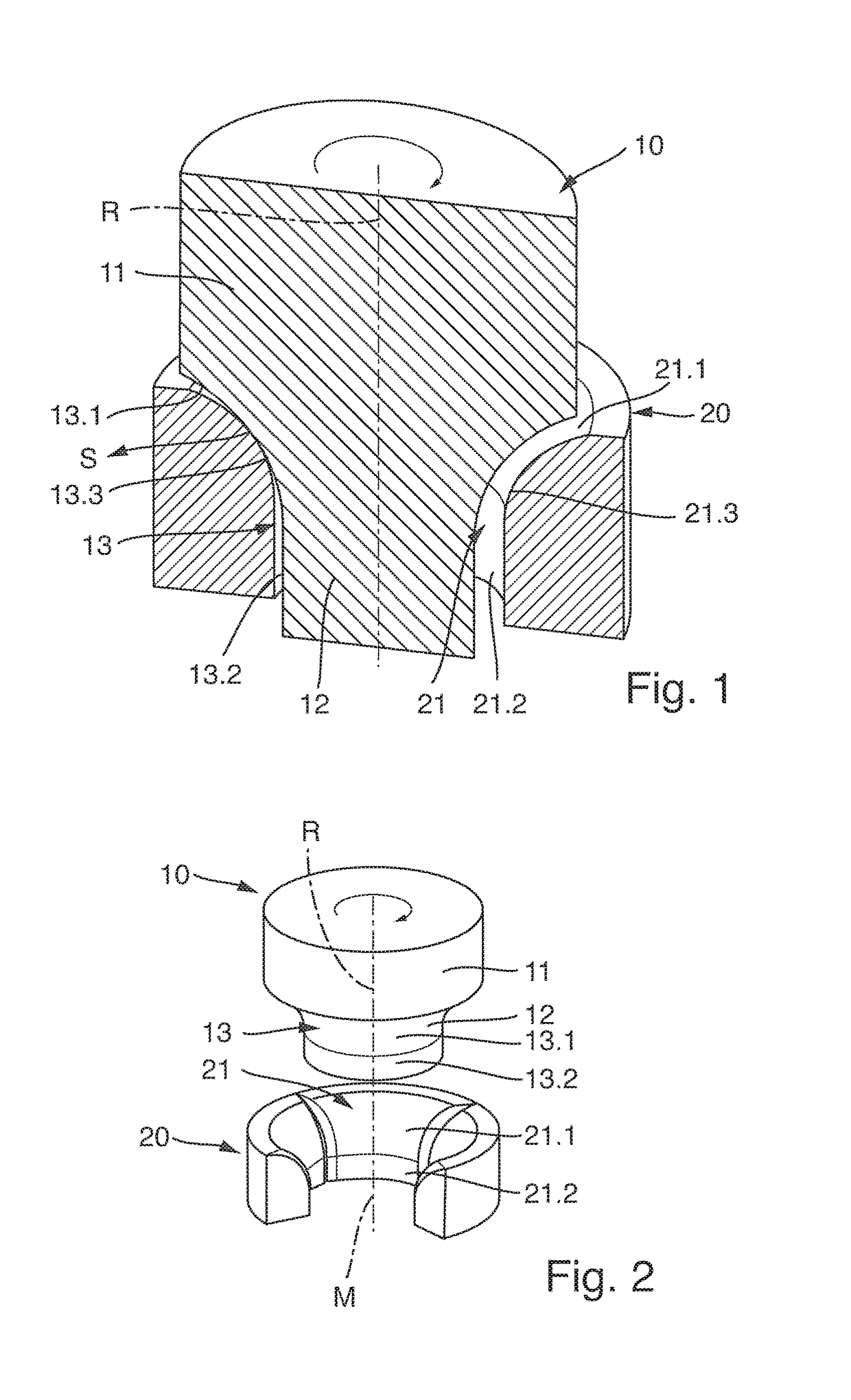
[0037]FIG. 1 and FIG. 2 show a hydrodynamic plain bearing having a rotor 10 and a stator 20, a sectioned depiction along rotor axis R of rotor 10 being selected. Rotor 10 possesses an attachment piece 11 adjoining which is a bearing segment 12. A machine component, for example a gear or the like, can be indirectly or directly coupled onto attachment piece 11. Bearing segment 12 possesses an, in particular, rotationally symmetrical rotor bearing surface 13. Rotor bearing surface 13 constitutes a continuous bearing contour in the direction of the rotation axis of the plain bearing. This bearing contour is constituted by two contour segments 13.1 and 13.2 and a transition segment 13.3. The distance of the bearing contour from the rotation axis can consequently vary along the rotation axis (longitudinal center axis) in the context of the invention.

[0038]According to the present invention and in particular as shown by the variant embodiment in accordance with FIG. 1, the bearing contour ...


PUM


Abstract

The invention relates to a hydrodynamic plain bearing having a stator and a rotor rotatable with respect to the stator, a rotor bearing surface being located opposite a counter-surface of the stator in order to generate hydrodynamic pressure. In order to achieve improved utilization properties, provision is made according to the present invention that the rotor bearing surface and / or the counter-surface constitutes in a section view, in the context of a section along and through the rotation axis, a continuous bearing contour that is constituted from at least two contour segments; that the contour segments are suitable for generating hydrodynamic load capacity in a radial and axial direction; that the contour segments are led into one another, by means of at least one transition segment, in such a way that hydrodynamic load capacity is generatable via the contour segments and the transition segment; and that the plain bearing is embodied as a multiple-surface plain bearing having two or more lubrication wedges in the region of the contour segments and of the transition segment).

Description

BACKGROUND OF THE INVENTION[0001]The invention relates to a hydrodynamic plain bearing having a stator and a rotor rotatable with respect to the stator, a rotor bearing surface being located opposite a counter-surface of the stator in order to generate hydrodynamic pressure.[0002]The invention further relates to an exhaust-gas-driven turbocharger having a hydrodynamic plain bearing.DESCRIPTION OF THE PRIOR ART[0003]Rotating machine elements, for example shafts, track rollers, gear wheels, or pump wheels, require guidance in a radial and axial direction so that forces and torques can be transferred. This task can be taken on by plain bearings that act hydrodynamically. The functionality of this type of bearing is based on the physical principle of hydrodynamic pressure generation. In hydrodynamic plain bearings, a suitable lubricant is held between the rotor and the stator. Upon a rotational motion of the rotor relative to the stator, shear forces are produced in the lubricant and th...

Claims


Application Information

Patent Timeline
Patent Type & Authority Applications(United States)
IPC IPC(8): F16C17/02F16C33/10
CPCF16C17/028F16C33/1075F01D25/166F16C17/10F05D2220/40F16C2360/24F16C27/02F16C17/047F16C17/18
Inventor KLEINSCHMIDT, RUEDIGERSTETTER, FRIEDERSCHMITT, STEFFENKUHNE, OLIVERBERGER, MARTIN
Owner BOSCH MAHLE TURBO SYST GMBH & CO KG
Why Eureka
Try Eureka