Turbocharger

Active Publication Date: 2021-12-14
BOSCH MAHLE TURBO SYST GMBH & CO KG
View PDF35 Cites 0 Cited by
  • Summary
  • Abstract
  • Description
  • Claims
  • Application Information

AI Technical Summary

Benefits of technology

[0016]The object of the invention is to furnish an exhaust-gas-driven turbocharger and a hydr

Problems solved by technology

The two bearing types must then each be calculated and designed separately from one another, resulting in correspondingly high costs for both design

Method used


Image

  • Turbocharger
  • Turbocharger
  • Turbocharger

Examples


Embodiment Construction

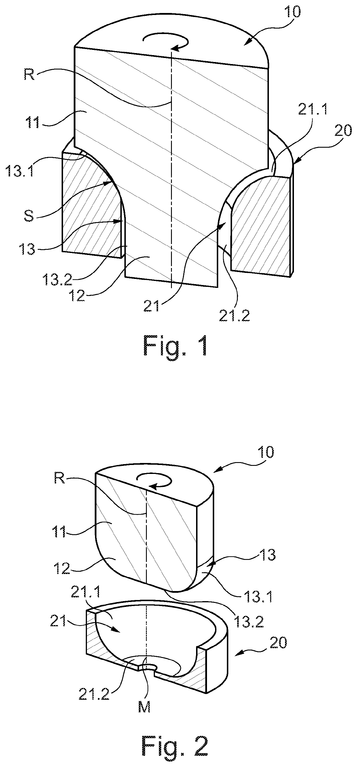
[0044]FIG. 1 shows a hydrodynamic plain bearing having a rotor 10 and a stator 20, a sectioned depiction along rotor axis R of rotor 10 being selected. Rotor 10 possesses an attachment piece 11 onto which a bearing segment 12 is attached. A machine component, for example a gear or the like, can be indirectly or directly coupled onto attachment piece 11. Bearing segment 12 possesses an, in particular, rotationally symmetrical rotor bearing surface 13. The rotor bearing surface constitutes a continuous bearing contour. This bearing contour is constituted by two contour segments 13.1 and 13.2, in such a way that the bearing contour is continuous. The distance of the bearing contour from the rotation axis can consequently vary along the rotation axis (longitudinal center axis) in the context of the invention.

[0045]In particular, as shown in FIG. 1, in the present exemplifying embodiment the bearing contour is continuously differentiable. With continuously differentiable bearing contours...


PUM


Abstract

The invention relates to an exhaust-gas-driven turbocharger having a hydrodynamic plain bearing having a rotor and a stator, the rotor being rotatable with respect to the stator, the rotor bearing surface being located opposite a counter-surface of the stator in order to generate hydrodynamic pressure in the region of a converging gap. In such a hydrodynamic plain bearing, the application properties can be improved by the fact that the rotor bearing surface and/or the counter-surface constitutes in a section view, in the context of a section along and through the rotation axis, a continuous bearing contour that is constituted from convex or concave curvatures and/or from at least two contour segments that are embodied as straight lines and/or curvatures. The invention also relates to a hydrodynamic plain bearing or bearing arrangement having such a plain bearing.

Description

BACKGROUND OF THE INVENTION(1) Field of the Invention[0001]The invention relates to an exhaust-gas-driven turbocharger having a hydrodynamic plain bearing having a rotor and a stator, the rotor being rotatable with respect to the stator, a rotor bearing surface being located opposite a counter-surface of the stator in order to generate hydrodynamic pressure in the region of a converging gap.[0002]The invention further relates to a bearing arrangement having a hydrodynamic plain bearing.[0003]Lastly, the invention relates to a hydrodynamic plain bearing.(2) Description of the Related Art[0004]Rotating machine elements, for example shafts, track rollers, gear wheels, or pump wheels, require guidance in a radial and axial direction so that forces and torques can be transferred. This task can be taken on by plain bearings that act hydrodynamically. The functionality of this type of bearing is based on the physical principle of hydrodynamic pressure generation. In hydrodynamic plain bear...

Claims


Application Information

Patent Timeline
IPC IPC(8): F16C17/18F16C17/10F16C33/10F01D25/16F02B37/00
CPCF16C17/18F01D25/16F01D25/166F02B37/00F16C17/10F16C17/105F16C33/1075F05D2220/40F05D2240/53F05D2250/323F05D2250/36F05D2250/711F05D2260/30F16C2202/08F16C2202/22F16C2360/24Y02T10/12F16C17/03
Inventor BERGER, MARTINKLEINSCHMIDT, RÜDIGERKROPP, MARTINJENNES, JÖRG
Owner BOSCH MAHLE TURBO SYST GMBH & CO KG
Why Eureka
Try Eureka