Apparatus and method for changing unwinding units in a wrapping machine, and unwinding apparatus

a technology of unwinding unit and unwinding apparatus, which is applied in the direction of wrapping/bundling articles, external supports, packaging, etc., can solve the problems of reducing machine productivity, laborious and slow, and determining the increase of the time required for the unwinding unit, so as to achieve compact and inexpensive

Inactive Publication Date: 2018-04-26
AETNA GROUP
View PDF24 Cites 7 Cited by
  • Summary
  • Abstract
  • Description
  • Claims
  • Application Information

AI Technical Summary

Benefits of technology

[0023]Another object is to provide an apparatus and a method that allows an automatic, rapid, and efficient replacement of an unwinding unit in a wrapping machine, in particular of the type with a rotating ring or arm, or of the rotating platform type.
[0026]Still another object is to provide an apparatus and a method that allows the unwinding unit to be reversibly mounted and locked to the wrapping machine.
[0027]A still further object is to make a wrapping machine that allows replacing an unwinding unit in an automatic, rapid, and efficient manner.
[0028]Another object is to provide a film unwinding apparatus that is removably associated with a wrapping machine and that allows replacing an unwinding unit in an automatic, rapid, and efficient manner.
[0030]Still another object is to provide an unwinding apparatus that is compact and inexpensive.

Problems solved by technology

These manual interventions, in addition to being heavy for the operator, require the presence and availability of the operator near the machine, in the case where the operator is absent or engaged in other activities, the replacement procedure can require machine downtimes that are also relatively long, with consequent reduction of the productivity of the machine.
However, the above-mentioned apparatuses have the drawback that they require the manual winding of the initial film flap of the new reel around the rollers of the unwinding unit in order to allow the proper start of the machine.
This preliminary winding operation, which is carried out manually, is laborious and slow, and determinates an increase of the time required for the reel replacement.
However, such apparatuses, while allowing the replacement of the reel in a completely automatic manner, without the need for a manual intervention by an operator, are not very reliable.
In particular, they do not ensure that the preliminary winding operation at each reel replacement is properly executed.
A drawback of the above-mentioned apparatuses is that the supports of the unwinding units have to be located adjacent to the machine to allow for the replacement of the unwinding units.
In such positions, the supports, due to their overall dimensions, can considerably limit the effectiveness of the wrapping machine, in particular, the mounting of optional units and / or optional accessories.
Such a drawback is particularly apparent in the case where the machine includes two or more unwinding units, and therefore a higher number of supports.
Such operations necessarily involve stopping the machine, thus reducing its productivity.
Another drawback is that mounting and dismantling the unwinding unit from the wrapping machine is very laborious and complex, since the procedure requires the movement of the wrapping machine, in particular of the ring or the rotating arm that supports the winding unit.
Furthermore, the coupling device, which is necessary to fix the unwinding unit to the wrapping machine, is complex and expensive.
A drawback of such replacement systems is that the above-mentioned unwinding units are equipped with film reel, motors, and pre-stretching and winding rollers which are very expensive and which necessitate at least two unwinding, units in order to allow for rapid replacement and a decreased downtime of the wrapping machine.

Method used


Image

  • Apparatus and method for changing unwinding units in a wrapping machine, and unwinding apparatus
  • Apparatus and method for changing unwinding units in a wrapping machine, and unwinding apparatus
  • Apparatus and method for changing unwinding units in a wrapping machine, and unwinding apparatus

Examples


Embodiment Construction

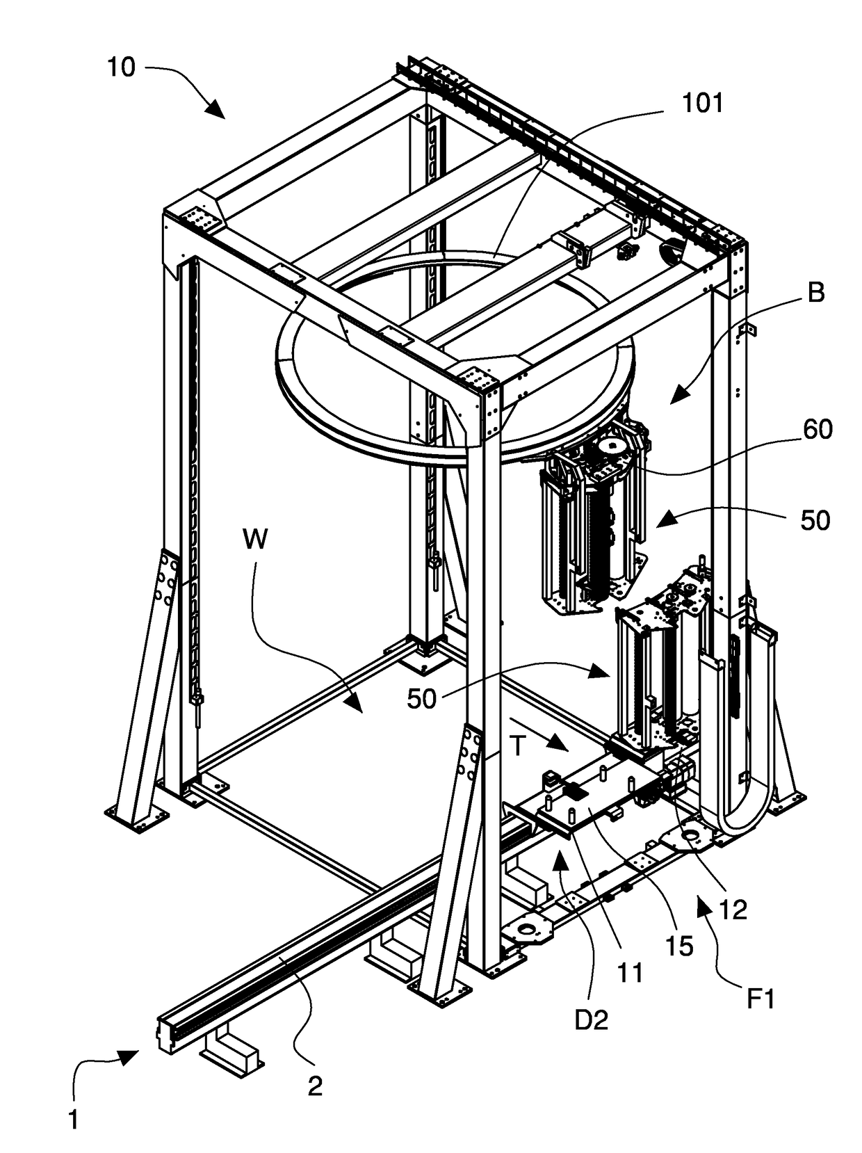
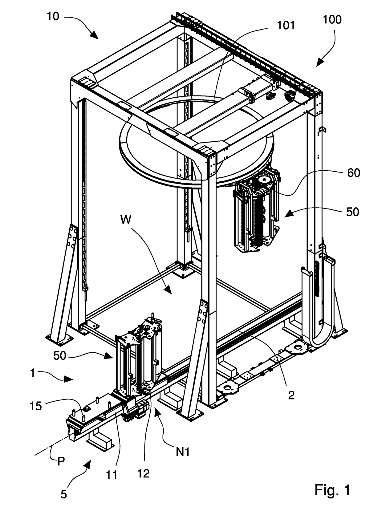
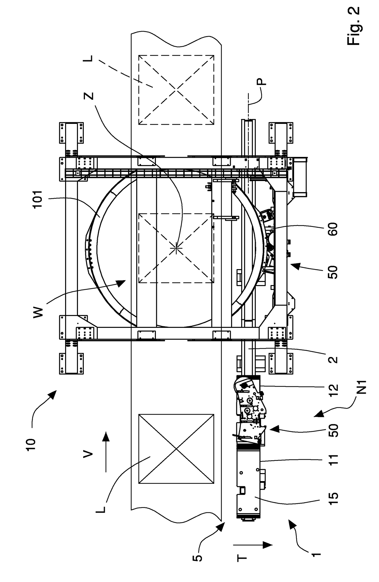
[0062]With reference to the FIGS. 1 to 3, there is illustrated the apparatus I according to the invention, arranged for changing unwinding units 50 of, and associated with a wrapping machine 10 for wrapping a load L with a film 4 of extensible synthetic plastic material.

[0063]The apparatus 1 of the invention includes at least one unwinding unit 50, a supporting unit 60 associated with the wrapping machine 10, and shuttles 11, 12 for moving the unwinding unit.

[0064]The wrapping machine 10 is, for example, provided with a horizontal ring 101, which is rotating around a vertical wrapping axis Z, and which is vertically movable so as to wrap the load L with helical coils or bands of film 4. The ring 101 is rotatably supported by a sliding frame (not illustrated) that is linearly movable along a vertical direction that is substantially parallel to the above-mentioned wrapping axis Z. On the ring 101, a supporting unit 60 is fixed, to which an unwinding unit 50 of the film 4 can be revers...


PUM

PropertyMeasurementUnit
wrapping angleaaaaaaaaaa
winding angleaaaaaaaaaa

Abstract

An apparatus associated with a wrapping machine includes at least one unwinding unit for the wrapping machine for wrapping a load with a film, and shuttles that are movable along a path and suitable for receiving and supporting an unwinding unit to be replaced and to be dismantled from the wrapping machine, or a new unwinding unit to be mounted on the wrapping machine. The shuttles operate along a substantially horizontal operating direction to dismantle and receive from the wrapping machine an unwinding unit to be replaced or to transfer and mount on the wrapping machine a new unwinding unit. The apparatus includes a supporting unit fixed to the wrapping machine and arranged to be coupled to, and supported by, the unwinding unit, the unwinding unit including a first coupling device, and the supporting unit including a second coupling device, the first coupling device and the second coupling device being mutually coupled or uncoupled along the operating direction.

Description

CROSS-REFERENCE TO RELATED APPLICATIONS[0001]This application is a division of U.S. patent application Ser. No. 14 / 238 497 filed Feb. 12, 2014. application Ser. No. 14 / 238,497 is a § 371 National Stage of PCT International Application No. PCT / IB2012 / 054125. PCT / IB2012 / 054125 claims priority to IT Application No. MO2011A000211 filed Aug. 16, 2011 and MO2011A000312 filed Dec. 1, 2011. The entire contents of these applications are incorporated herein by reference.BACKGROUND OF THE INVENTION[0002]The invention relates to machines and methods for wrapping a load with a film of extensible synthetic plastic material. In particular, the invention relates to an apparatus and a method for automatically changing a film unwinding unit that is mounted on a wrapping machine. The invention further relates to a wrapping machine including such apparatus and to a film unwinding apparatus removably associated with a wrapping machine and a wrapping machine including such unwinding apparatus.BRIEF DESCR...

Claims


Application Information

Patent Timeline
Patent Type & Authority Applications(United States)
IPC IPC(8): B65B11/02B65B59/04B65B11/04
CPCB65B11/025B65B59/04B65B11/045B65B2011/002B65B41/16B65B2210/18
Inventor CERE', MAUROCASALBONI, MIRKO
Owner AETNA GROUP
Why Eureka
Try Eureka