
Pondage device

a technology of pondage device and support, which is applied in dams, construction, marine site engineering, etc., can solve the problems of insufficient accuracy, complex and delicate determination of support positioning, and extensive numerical modeling

Inactive Publication Date: 2018-05-03
ELECTRICITE DE FRANCE
View PDF0 Cites 1 Cited by
  • Summary
  • Abstract
  • Description
  • Claims
  • Application Information

AI Technical Summary

Benefits of technology

The patent is about a new invention that can control the forces exerted by a hydraulic dam's downstream wall on its downstream improvement, either autonomously or in a controlled manner. The invention is simple to model and monitor and can be used underwater with dams that have a downstream water level. The invention also offers an interface means that is less expensive than known prior art devices.

Problems solved by technology

However, this technique poses the following problems:the determination of the positioning of the supports is complex and delicate; it requires extensive numerical modeling, the accuracy whereof can prove insufficient;the forces transferred by the dam to the improvement depend on its horizontal displacements.
The latter being low at the foot, little force can be transferred at the foot, which is the zone subjected to the highest hydrostatic pressure on the part of the pondage;it can be necessary to re-position the supports over time in the event of irreversible change in the behavior of the dam and / or of its foundation;the initial bearing of the dam on the improvement, like any change in bracing, requires prior relief of the dam by draining the pondage;this type of support requires strong and costly monitoring; it cannot be implemented underwater.

Method used


Image

  • Pondage device
  • Pondage device
  • Pondage device

Examples


Embodiment Construction

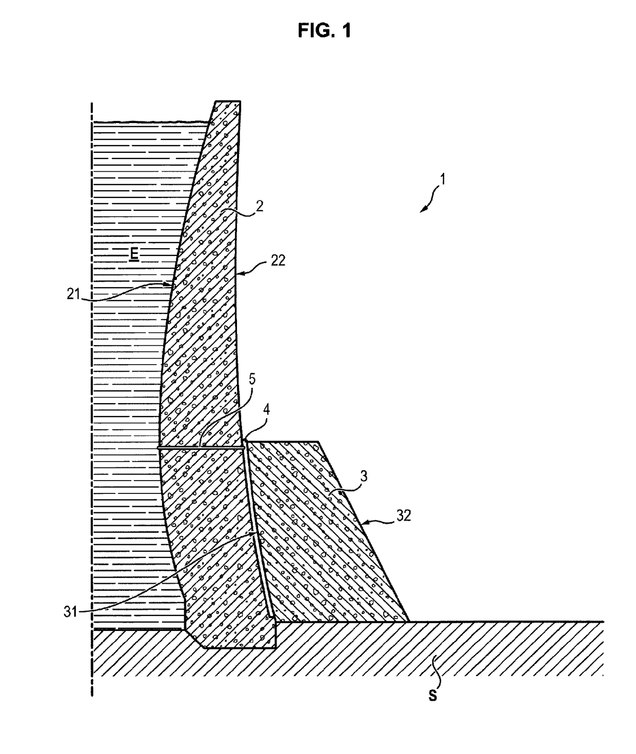
[0054]The pondage device conforming to the invention will now be described with reference to FIG. 1. In this figure, the pondage device 1 comprising a dam 2 and an improvement 3 can be seen.

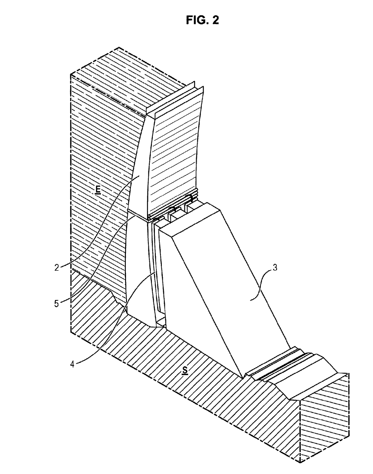
[0055]Preferably, the dam 2 is an arch dam, made of concrete, that is a dam with an arched shape, the concavity whereof faces downstream, which allows a portion of the forces due to the pressure of the water to be transferred to the banks, rather than to the dam itself.

[0056]The dam 2 rests on the ground S and has an upstream facing 21, facing the water E retained by the dam 2, and a downstream facing 22, located opposite.

[0057]The improvement 3 is a reinforcement structure, preferably made of concrete, positioned on the downstream side of the dam, generally but not compulsorily of smaller height than the dam 2 and which is intended to relieve the dam of a portion of the hydrostatic pressure to which it is subjected by the pondage E.

[0058]The improvement 3 also rests on the ground S and has an up...


PUM


Abstract

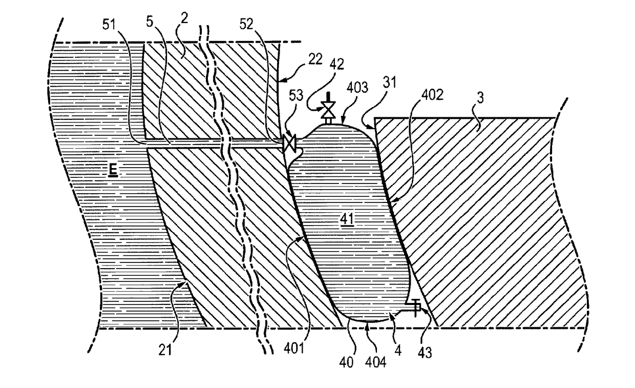
The invention relates to a pondage device (1) including a dam (2) and an improvement (3), arranged downstream from said dam, referred to as a “downstream improvement”. Said device is characterised in that it includes at least one flexible cylinder (4) positioned between said dam (2) and said improvement (3), and in that said flexible cylinder (4) includes a chamber (41) inside of which water is stored, said chamber being at least partially defined by a deformable membrane (40), said chamber (41) being kept under pressure by pressurisation means (5).

Description

GENERAL TECHNICAL FIELD[0001]The invention is situated in the field of hydraulic pondage.[0002]It relates more precisely to a pondage device comprising a dam, a downstream improvement which bears against the downstream wall of this dam through a support device making it possible to control the forces exerted by the downstream wall of the dam on said improvement.[0003]The unsatisfactory behavior of certain dams, as well as the evolution of regulatory requirements, particularly in term of protection against floods and earthquakes, can make it necessary to increase the resistance of these dams to extreme loads, or even to advantageously increase their lifetime.[0004]One solution consists of accomplishing structural improvements of these dams, so as to restore in them safety margins sufficient to resist these extreme loads.[0005]These improvements can for example be accomplished by means of a downstream structure, called a “downstream improvement,” on which the existing dam bears. In th...

Claims


Application Information

Patent Timeline
Patent Type & Authority Applications(United States)
IPC IPC(8): E02B8/00E02B7/12
CPCE02B8/00E02B7/12E02B7/08
Inventor LOCHU, ALEXANDRE
Owner ELECTRICITE DE FRANCE
Learn More