Process for gear manufacturing machining

Active Publication Date: 2018-06-14
LIEBHERR VERZAHNTECHNIK GMBH
View PDF10 Cites 2 Cited by
  • Summary
  • Abstract
  • Description
  • Claims
  • Application Information

AI Technical Summary

Benefits of technology

The process in this patent has the advantage of being able to remove material from both the tooth flanks and the root at the same time, instead of separating the removal according to different surfaces. This results in a more efficient and precise procedure, avoiding unnecessary material removal on the tooth flanks or disfavored material removal in the root.

Problems solved by technology

In this case, the two or more additional conditions can, however, typically no longer be exactly satisfied.
This could have the result that a technologically unfavorably large material removal would take place in the root or that an unnecessarily small material removal would have to be selected on the tooth flanks.

Method used


Image

  • Process for gear manufacturing machining
  • Process for gear manufacturing machining
  • Process for gear manufacturing machining

Examples


Embodiment Construction

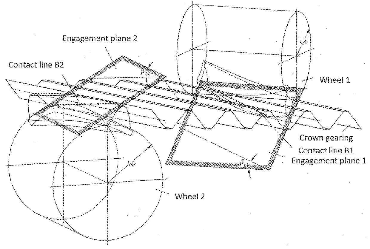
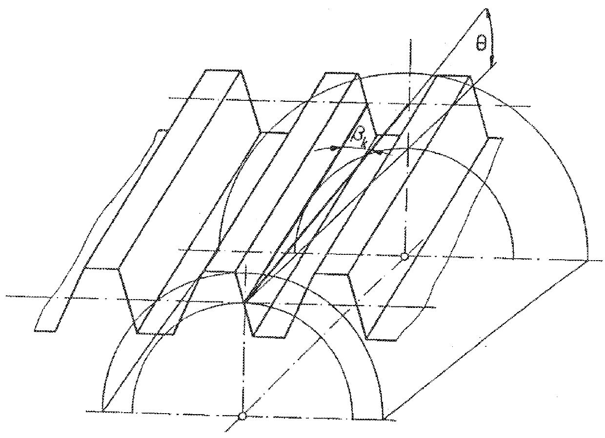
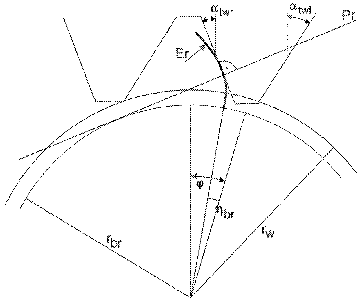
[0089]The invention describes a process for producing gearing arrangements. The production takes place using a toothed tool that forms a continuous generating gear train, i.e. a gear train with crossed axes, with the workpiece. The workpiece and the tool can each be both cylindrical and conical. Conical tools or conical workpieces are characterized by different leads on the left and right flanks and are frequently also called beveloids. In the cylindrical case, the leads are identical on both flanks. The profiles of the workpieces and of the tools can be both symmetrical and asymmetrical, that is the profile angles on the left and right flanks can be different. The tool can have both defined edges and non-defined edges. In the case of a non-defined edge, the enveloping gearing of the tool is to be considered in the following calculations. The production methods in which the process described here can inter alia be used are in particular continuous generating grinding, gear hobbing, ...


PUM

PropertyMeasurementUnit
Thicknessaaaaaaaaaa
Angleaaaaaaaaaa
Shapeaaaaaaaaaa

Abstract

The present invention shows a process for gear manufacturing machining a workpiece by a tool on a gear manufacturing machine, wherein the workpiece is machined by a generating machining process in which the tool for gear manufacturing machining rolls off on the workpiece at a predefined center distance and axial cross angle, wherein the gear manufacturing machining preferably takes place on two flanks, with a desired tooth trace shape and / or tooth thickness of the gearing being generated by the generating machining process. The process is characterized in that an additional condition is predefinable and in that the center distance and the axial cross angle are determined in dependence on the desired tooth trace shape and / or tooth thickness of the gearing and on the additional condition.

Description

CROSS-REFERENCE TO RELATED APPLICATION[0001]The present application claims priority to German Patent Application No. 10 2016 005 257.0, entitled “PROCESS FOR GEAR MANUFACTURING MACHINING,” filed on Apr. 28, 2016, the entire contents of which is hereby incorporated by reference in its entirety for all purposes.TECHNICAL FIELD[0002]The present invention relates to a process for gear manufacturing machining of a workpiece by a tool on a gear manufacturing machine. A workpiece is in this respect machined by a generating machining method in which the tool for the gear manufacturing machining rolls off on the workpiece at a predefined center distance and axial cross angle.BACKGROUND AND SUMMARY[0003]In a generating machining method, the rotational movements of the tool and of the workpiece are coupled such that the gear teeth of the tool roll off on the gear teeth of the workpiece, the so-called generating coupling. The generating movement thus corresponds to that of a gear train formed b...

Claims


Application Information

Patent Timeline
IPC IPC(8): B23F5/04B23F19/00B23F21/02B23F23/00G01B5/008G05B19/29G05B19/4093
CPCB23F5/04B23F19/002B23F21/026B23F23/006G01B5/008G05B19/29G05B19/40937G05B2219/35035G05B2219/36198B23F5/00B23F23/1225B23F1/02G05B19/186G05B19/41B23F5/20B23F5/02B23F21/16B24B53/075
Inventor WUERFEL, ROBERT
Owner LIEBHERR VERZAHNTECHNIK GMBH
Why Eureka
Try Eureka