Surface acoustic wave filter

Active Publication Date: 2007-03-29
SKYWORKS PANASONIC FILTER SOLUTIONS JAPAN
View PDF5 Cites 11 Cited by
  • Summary
  • Abstract
  • Description
  • Claims
  • Application Information

AI Technical Summary

Benefits of technology

[0020] A SAW filter of the present invention is formed by such a configuration that a SAW filter with the above-mentioned configuration is used as one SAW element, and these SAW elements are connected in multiple stages. According to this configuration, it is possible to easily obtain a SAW filter having a targeted characteristic, and it is also possible to enlarge a freedom degree of design.
[0021] According to the present invention, by arranging a plurality of SAW resonators in proximity

Problems solved by technology

Such a configuration that electrode fingers are arranged almost continuously means that they are arranged in such a manner th

Method used


Image

  • Surface acoustic wave filter
  • Surface acoustic wave filter
  • Surface acoustic wave filter

Examples


first embodiment

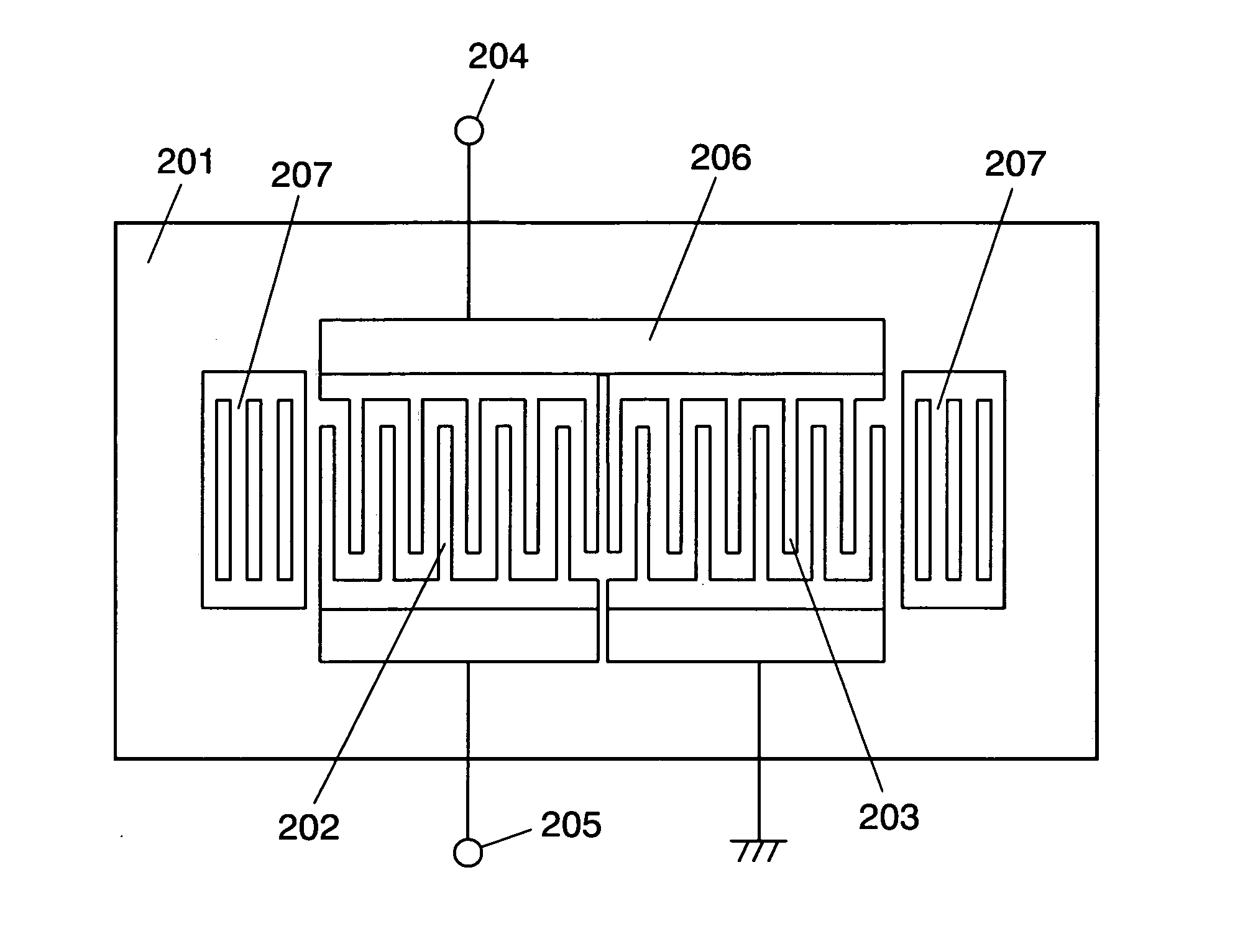
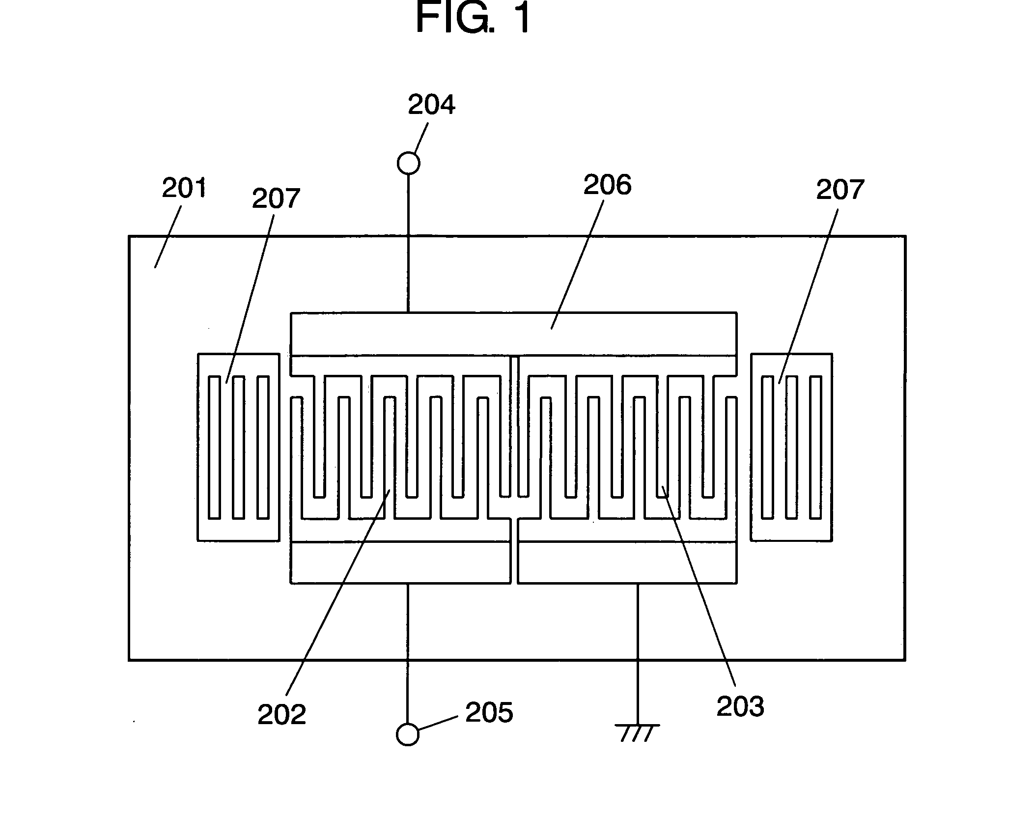
[0045]FIG. 1 is a plan view showing a configuration of a SAW filter which relates to a first embodiment. In general, a SAW filter is packaged by ceramic, resin etc., and used, but FIG. 1 shows only a configuration on a piezoelectric substrate 201. As shown in FIG. 1, in case of a SAW filter of this embodiment, it is composed by such a configuration that first IDT 202 and second IDT 203 are arranged on a surface of piezoelectric substrate 201 which is formed by lithium tantalate (LiTaO3) of 39° Y-cut X propagation in such a manner that they are on the same propagation path, reflector electrodes 207 are disposed on respective end portions.

[0046] First IDT 202 is arranged between one terminal 204 and the other terminal 205 of input / output terminals, i.e., serially to a signal path, and can carry out an operation which is equivalent to that of SAW resonators of a serial arm. Second IDT 203 is arranged in parallel to the signal path from a portion between one terminal 204 of the input / o...

second embodiment

[0092]FIG. 18 is a plan view showing a configuration of a SAW filter which relates to a second embodiment of the present invention. A different point between the SAW filter of this embodiment and the SAW filter of the first embodiment is such a point that an L type configuration was mainly used in the first embodiment, whereas in this embodiment, a π type configuration is mainly used.

[0093] The SAW filter of this embodiment is configured by first IDT 702, second IDT 703, third IDT 704 on piezoelectric substrate 701, and reflector electrodes 709 arranged on both ends.

[0094] First IDT 702 is arranged between one terminal 705 of input / output terminals and other terminal 706 of the input / output terminals, i.e., serially to a signal path. By this arrangement, this first IDT 702 can carry out an operation which is equivalent to that of SAW resonators of a serial arm. Second IDT 703 is arranged in parallel to a signal path from a portion between one terminal 705 of input / output terminals...

third embodiment

[0104]FIG. 19 is a plan view showing a configuration of a SAW filter which relates to a third embodiment of the present invention. A different point between the SAW filter of this embodiment and the SAW filter of the first embodiment is that an L type configuration is used in the first embodiment, and a T type configuration is used in this embodiment. As shown in FIG. 19, the SAW filter of this embodiment is configured by first IDT 802, second IDT 803, fourth IDT 804 on piezoelectric substrate 801 and reflector electrodes 808 arranged on both end portions.

[0105] First IDT 802 and fourth IDT 804 are arranged between one terminal 805 of input / output terminals and other terminal 806 of the input / output terminals, i.e. serially to a signal path. By this configuration, these things can carry out an operation which is equivalent to that of SAW resonators of a serial arm.

[0106] Second IDT 803 is arranged in parallel to a signal path from a portion between first IDT 802 and fourth IDT 804...


PUM


Abstract

It is configured by forming first IDT (202) and second IDT (203) on piezoelectric substrate (201), and first IDT (202) is arranged between one terminal (204) of input/output terminals and other terminal (205) of the input/output terminals, i.e., serially to a signal path, and second IDT (203) is arranged in parallel to a signal path from a portion between one terminal (204) of the input/output terminals and first IDT (202). First IDT (202) and second IDT (203) are arranged in proximity to each other on the same propagation path of surface acoustic waves which are excited by respective resonators.

Description

TECHNICAL FIELD [0001] This invention relates to a surface acoustic wave filter which is used for a communication device etc. such as a portable telephone. BACKGROUND ART [0002] In recent years, along with development of mobile communication, realization of high performance and miniaturization of devices to be used have been desired. As a filter for a mobile communication device among those devices, conventionally, a surface acoustic wave filter (hereinafter, called as a SAW filter) has been used widely. At the present day, as a SAW filter for an RF (Radio Frequency) stage, a longitudinal mode type and a ladder mode are mainly used. In particular, as to the ladder type SAW filter, it is possible to realize a low loss as compared with the longitudinal mode SAW filter. The ladder type SAW filter is of such a configuration that a plurality of surface acoustic wave resonators (hereinafter, called as SAW resonators) are connected in a ladder mode, and configured by SAW resonators operati...

Claims


Application Information

Patent Timeline
IPC IPC(8): H03H9/64H03H9/02
CPCH03H9/0274H03H9/14588H03H9/6473H03H9/6436H03H9/6426H03H9/00H03H9/64
Inventor NISHIMURA, KAZUNORIIGAKI, TSUTOMUMATSUNAMI, KENNAKAMURA, HIROYUKI
Owner SKYWORKS PANASONIC FILTER SOLUTIONS JAPAN
Why Eureka
Try Eureka