Permanent magnet and method for preparation thereof

Inactive Publication Date: 2004-06-24
SUMITOMO SPECIAL METAL CO LTD
View PDF2 Cites 2 Cited by
  • Summary
  • Abstract
  • Description
  • Claims
  • Application Information

AI Technical Summary

Benefits of technology

0136] A method for producing a ferrite magnet according to the present invention is characterized by preparing a magnetic body including, as a main phase, a ferrite having an M-type magnetoplumbite structure and represented by (1-x)AO.(x/2)R.sub.2O.sub.3.n Fe.sub.2O.sub.3 (where A is at least one element selected from the group consisting of Sr, Ba, Pb and Ca and R is at least one element selected from the group consisting of the rare-earth elements (including Y) and Bi and always includes La) and then adding an oxide of element M (which is at least one element selected from the group con

Problems solved by technology

However, none of these ferrite magnets can improve the magnetic properties sufficiently and reduce the manufacturing cost significantly at the same time.
However, the properties of such a ferrite are still not fully satisfactory.
But if a rare-earth element (such as La) and Co are used in large amounts as substi

Method used


Image

  • Permanent magnet and method for preparation thereof
  • Permanent magnet and method for preparation thereof
  • Permanent magnet and method for preparation thereof

Examples


example 2

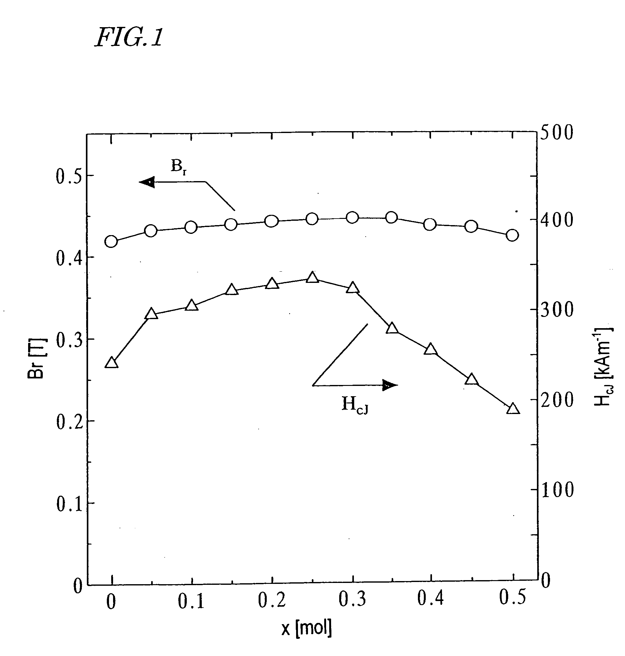
[0147] First, as in the first example described above, a calcined body magnet powder with a composition (1-x)SrO.(x / 2)La.sub.2O.sub.3.n Fe.sub.2O.sub.3 was prepared so as to satisfy 0.ltoreq.x.ltoreq.0.5 and n=6.2.

[0148] This calcined body powder was analyzed by an X-ray diffraction method. As a result, in a range where x.ltoreq.0.35 was satisfied, an M-type ferrite single phase was identified. However, in a range where x.gtoreq.0.4 was satisfied, not only the M-phase but also an ortho-ferrite phase and a hematite phase were identifiable.

[0149] A CoO powder was added to this calcined body magnet powder such that the mole fraction y of the element M in the oxide of the element M to be added to one mole of the calcined body magnet powder satisfied 0.ltoreq.y.ltoreq.0.25 (i.e., y / x=0.5). Also, 0.7 wt % of CaCO.sub.3 powder and 0.4 wt % of SiO.sub.2 powder were further added thereto. After that, a sintered body was obtained as in the first example described above.

[0150] B.sub.r and H.su...

example 3

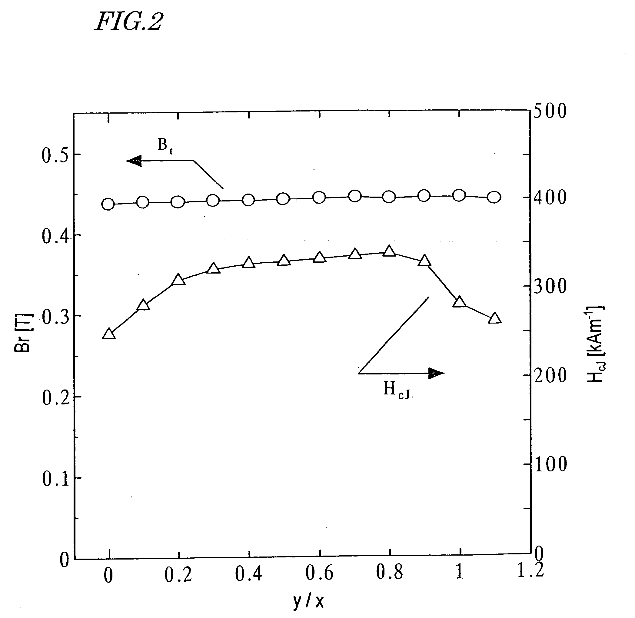
[0152] First, as in the first example described above, an M-type ferrite calcined body magnet powder with a composition (1-x)SrO.(x / 2)La.sub.2O.su-b.3 n Fe.sub.2O.sub.3 was prepared so as to satisfy x=0.2 and n=6.2.

[0153] A CoO powder was added to the M-type ferrite calcined body magnet powder during the fine pulverization process such that the mole fraction y of the element M in the oxide of the element M to be added to one mole of the calcined body magnet powder satisfied 0.ltoreq.y.ltoreq.0.22 (i.e., 0.ltoreq.y / x.ltoreq.1.1). After that, a sintered body was obtained as in the first example described above.

[0154] B.sub.r and H.sub.cJ of the resultant sintered magnet were measured. The results of measurement are shown in FIG. 2. As can be clearly seen from FIG. 2, H.sub.cJ increased in a range where 0.2.ltoreq.y / x.ltoreq.0.8 was satisfied and B.sub.r increased in a range where 0.2.ltoreq.y / x.ltoreq.1.0 was satisfied.

[0155] The magnetic properties were also tested as in the method d...

example 4

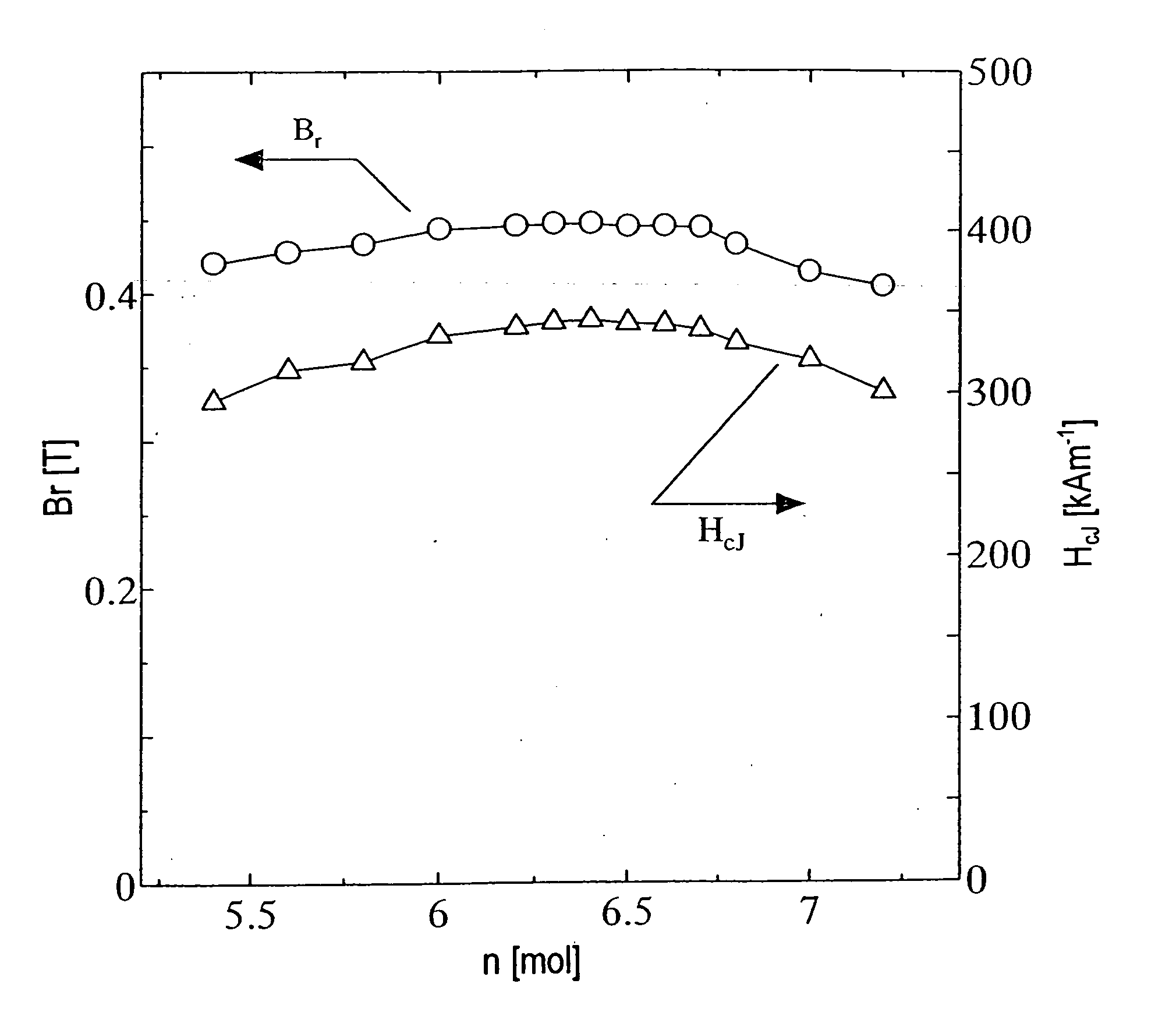
[0156] A calcined body magnet powder was prepared as in the first example described above except that respective materials were mixed together so as to satisfy x=0.2 and 5.4.ltoreq.n.ltoreq.7.2 in the composition (1-x)SrO.(x / 2)La.sub.2O.sub.3.n Fe.sub.2O.sub.3. Then, a sintered body was made of the calcined body magnet powder as in Sample No. 1 of the first example.

[0157] The resultant calcined body powder was analyzed by an X-ray diffraction method. As a result, in a range where 5.0

[0158] B.sub.r and H.sub.cJ of the resultant sintered magnet were measured. The results of measurement are shown in FIG. 3. As can be clearly seen from FIG. 3, B.sub.r and H.sub.cJ increased in a range where 6.0

[0159] The magnetic properties were also tested as in the method describe...


PUM

PropertyMeasurementUnit
Angleaaaaaaaaaa
Angleaaaaaaaaaa
Angleaaaaaaaaaa

Abstract

A ferrite magnet obtained by adding at least one element selected from the group consisting of Co, Ni, Mn and Zn to a ferrite having a hexagonal M-type magnetoplumbite structure, in which a portion of Sr, Ba, Pb or Ca is replaced with at least one element that is selected from the group consisting of the rare-earth elements (including Y) and Bi and that always includes La, during the fine pulverization process thereof, and then subjecting the mixture to re-calcining and/or sintering process(es). By adding a small amount of the element such as Co, Ni, Mn or Zn to the ferrite already having the hexagonal M-type magnetoplumbite structure during the fine pulverization process thereof, the magnetic properties can be improved.

Description

[0001] The present invention relates to a ferrite magnet powder, a magnet made of the magnet powder, and methods of making the magnet powder and the magnet.[0002] Ferrite is a generic term for any compound including an oxide of a divalent cationic metal and trivalent iron, and ferrite magnets have found a wide variety of applications in numerous types of rotating machines, loudspeakers, and so on. Typical materials for a ferrite magnet include Sr ferrites (SrFe.sub.12O.sub.19) and Ba ferrites (BaFe.sub.12O.sub.19) having a hexagonal magnetoplumbite structure. Each of these ferrites is made of iron oxide and a carbonate of strontium (Sr), barium (Ba) or any other suitable element, and can be produced at a relatively low cost by a powder metallurgical process.[0003] A basic composition of an (M-type) ferrite having the magnetoplumbite structure is normally represented by the chemical formula AO.6Fe.sub.2O.sub.3, where A is a metal element to be divalent cations and is selected from th...

Claims


Application Information

Patent Timeline
IPC IPC(8): C01G49/00C04B35/26G11B5/706H01F1/11H01F1/113H01F41/02
CPCC01G49/009Y10T428/32C01P2002/76C01P2004/61C01P2004/62C01P2006/42C04B35/2641C04B35/2683C04B35/6262C04B2235/3208C04B2235/3213C04B2235/3217C04B2235/3227C04B2235/3241C04B2235/3263C04B2235/3274C04B2235/3275C04B2235/3279C04B2235/3284C04B2235/3418C04B2235/421C04B2235/44C04B2235/448C04B2235/5445C04B2235/605C04B2235/767C04B2235/81G11B5/70678H01F1/11H01F1/113C01P2002/30
Inventor ODA, ETSUSHITOYOTA, SACHIOHOSOKAWA, SEIICHI
Owner SUMITOMO SPECIAL METAL CO LTD
Why Eureka
Try Eureka