Display optical system, image display apparatus, image taking optical system, and image taking apparatus

Inactive Publication Date: 2006-03-14
CANON KK
View PDF99 Cites 11 Cited by
  • Summary
  • Abstract
  • Description
  • Claims
  • Application Information

AI Technical Summary

Benefits of technology

[0020]In addition, in both the display optical system and the image taking optical system, it is preferable to form a surface for reflecting and returning light as a curved surface. If the return reflection surface is a plane, since directions of rays of images around it cannot be controlled respectively at the time of reflection, the optical system tends to be large. If the return reflection surface is a rotation asymmetrical surface, since directions of rays of images around it can be controlled freely, it is possible to further miniaturize the optical system compared with the case of a curved surface.
[0021]Moreover, the second surface (return reflection surface) is formed as a reflective member separate from the optical element having the first and second surfaces, whereby the number of effective surfaces in an optical path can be increased without affecting sizes of the display optical system and the image taking optical system. Thus, it becomes possible to increase a degree of freedom of design and to realize improvement of an optical performance.
[0022]Moreover, a reflective member is formed as a rear surface mirror having a transmission surface and a reflection surface, whereby the transmission surface can also be used

Problems solved by technology

In general, an optical system of a type in which an intermediate image is once formed h

Method used


Image

  • Display optical system, image display apparatus, image taking optical system, and image taking apparatus
  • Display optical system, image display apparatus, image taking optical system, and image taking apparatus
  • Display optical system, image display apparatus, image taking optical system, and image taking apparatus

Examples


Example

First Embodiment

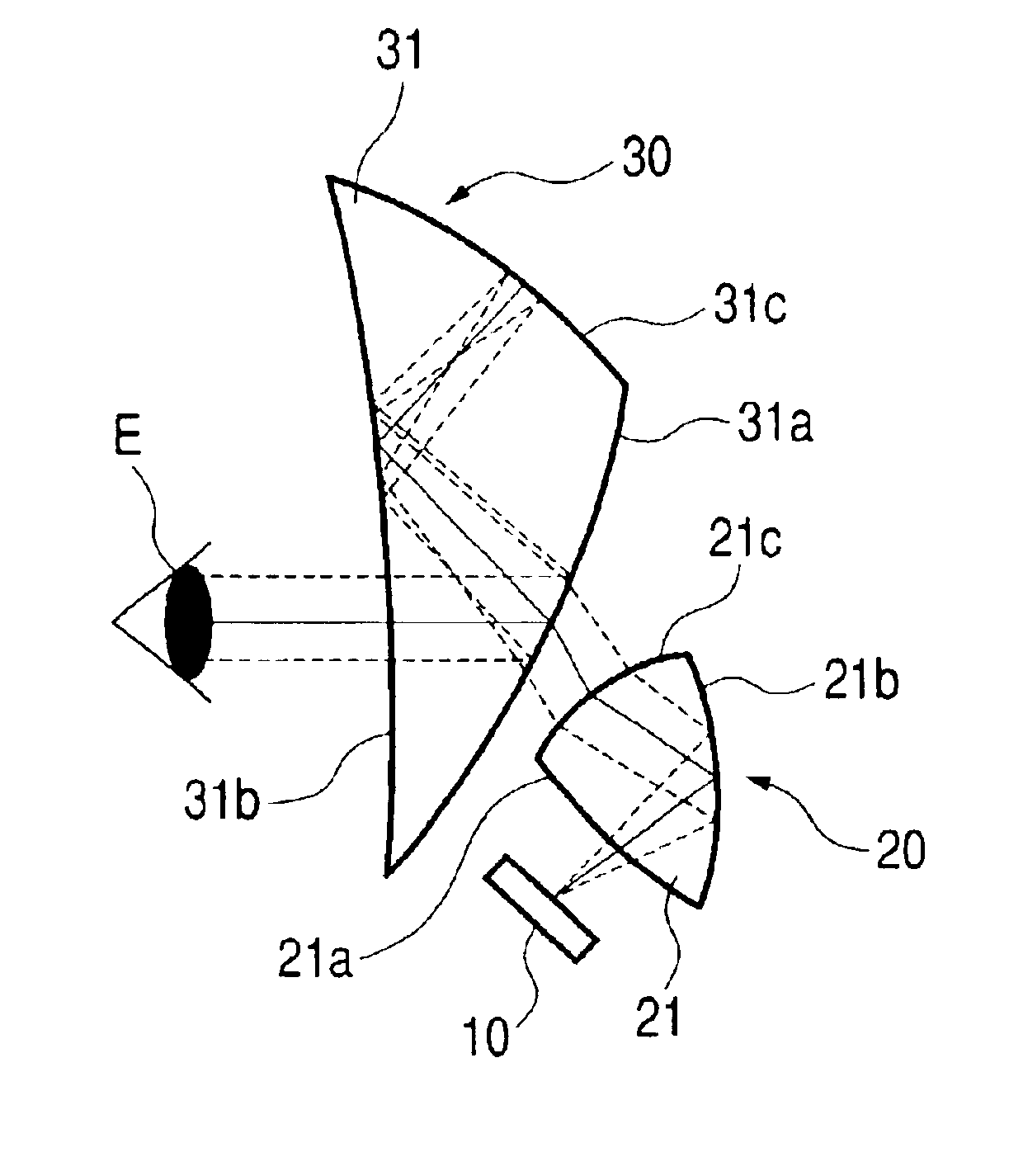
[0056]FIG. 1 shows a display optical system that is first Embodiment of the present invention. This display optical system is constituted by a first optical system 30 having positive optical power (1 / focal length) as a whole and a second optical system 20 having positive optical power as a whole which are arranged in order from a side of an eye E of an observer toward an image display device (LCD, etc.) 10.

[0057]In this embodiment, both the first optical system 30 and the second optical system 20 are constituted with optical surfaces formed on transparent bodies (hereinafter referred to as optical elements, respectively) 31 and 21 the inside of which is filled with an optical medium such as glass or plastics.

[0058]Light modulated and emitted by the image display device 10 is incident on the second optical element 21 from a surface 21a, reflected on a surface 21b and transmitted through a surface 21c to exit the second optical element 21. The light that has exit the s...

Example

Second Embodiment

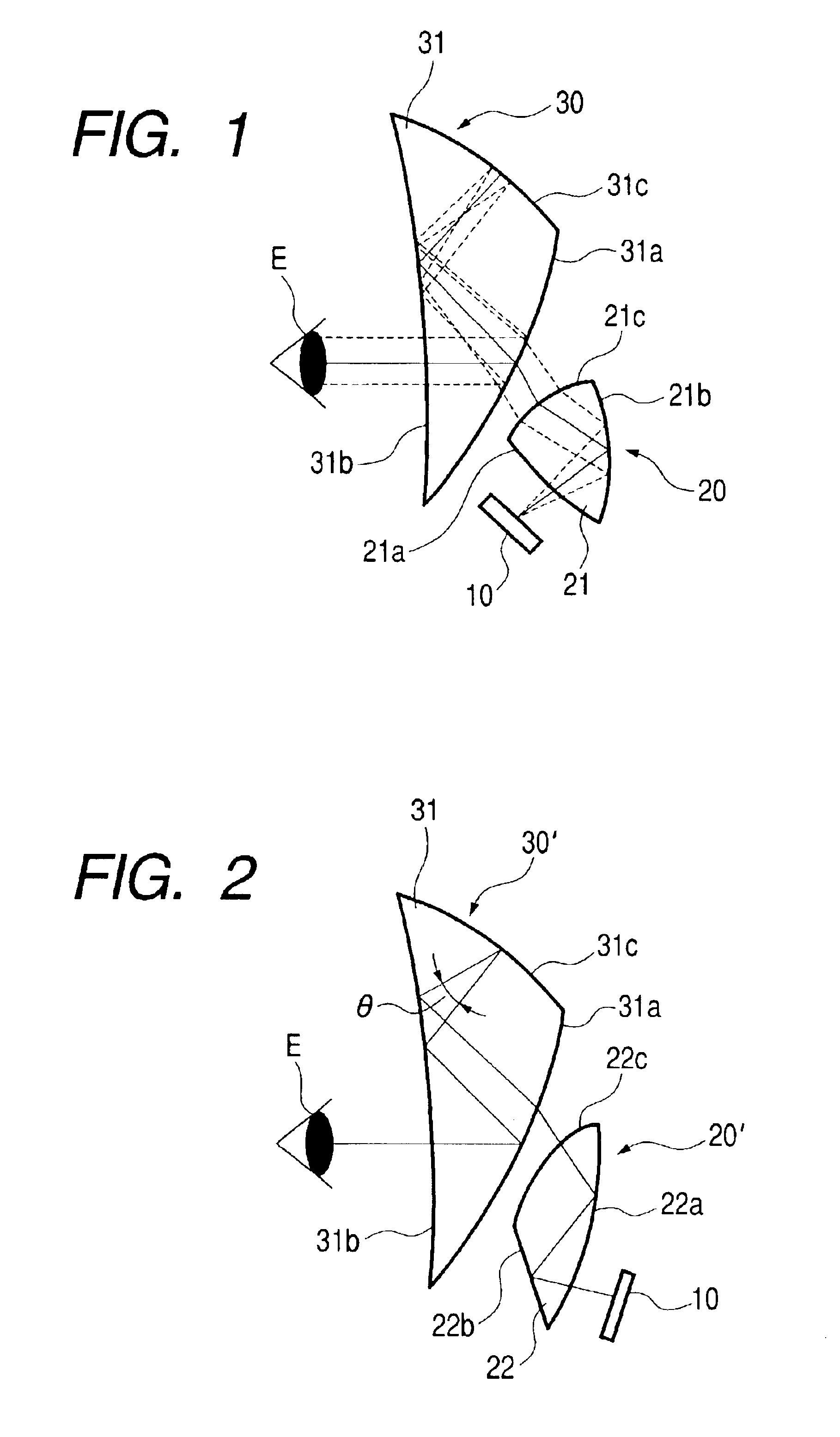
[0080]FIGS. 2 and 3 show display optical systems that are second Embodiment of the present invention. First optical systems 30′ and 30″ and second optical systems 20′ and 20″, which constitute the display optical system of this embodiment, are different from those in first Embodiment.

[0081]In the display optical system shown in FIG. 2, light emitted from an image display device 10 is incident on an optical element (second optical element) 22 constituting the second optical system 20′ from a surface 22a, reflected on a surface 22b, totally reflected on the surface 22a and exits the second optical element 22 from a surface 22c. The light that has exit the second optical system 20′ from the exit surface 22c is incident on a transparent body (first optical element) 31 constituting the first optical system 30′ from a surface 31a.

[0082]The light incident on the first optical element 31 from the incident surface 31a is reflected on a surface 31b, returned and reflected on...

Example

Third Embodiment

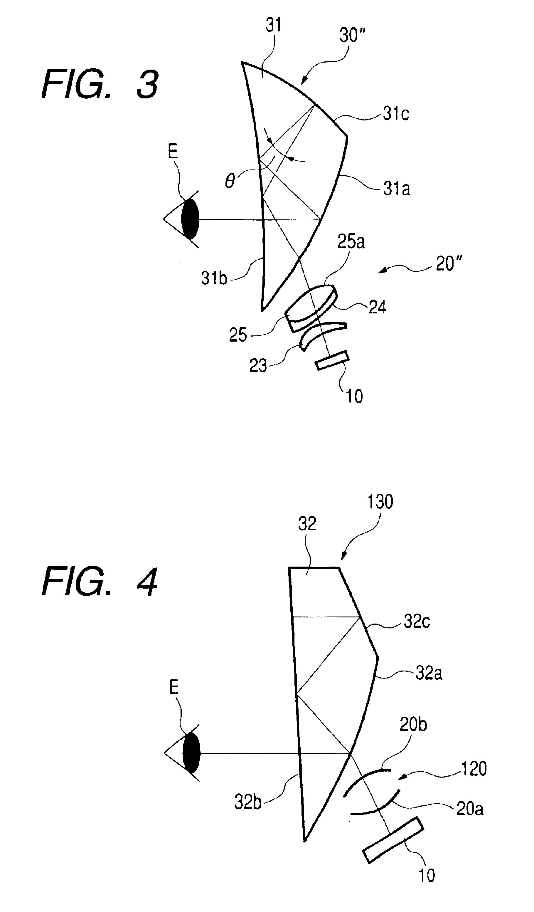
[0092]FIG. 4 shows a display optical system that is third Embodiment of the present invention. For ease of understanding, a second optical system is simplified. A display optical system may be constituted by being combined with the second optical systems shown in FIGS. 1 to 3, respectively.

[0093]The display optical system of this embodiment is constituted by a first optical system 130 having positive optical power (1 / focal length) as a whole and a second optical system 120 having positive optical power as a whole which are arranged in order from a side of an eye E of an observer toward an image display device (LCD, etc.) 10.

[0094]In this embodiment, the first optical system 130 is constituted with an optical surface formed on a transparent body (first optical element) 32 the inside of which is filled with an optical medium such as glass or plastics.

[0095]Light modulated and emitted by the image display device 10 is incident on the second optical system 120 from an in...


PUM


Abstract

A display optical system for guiding light from an image to an observer or a surface projecting an image thereon with a first optical system and second optical system. The first optical system having a first surface formed on a transparent body with a reflecting action, a second surface reflecting light reflected on the first surface toward the first surface again, and a third surface formed on the transparent body transmitting light from the image. The light transmitted through the third surface travels toward the first surface and is reflected for the first time. In addition, a principal ray, central angle of view to be reflected for the last time on the first surfaces is reflected to a side opposite a side of the first reflection on the first surface with respect to a normal line of a surface on a hit point thereof.

Description

FIELD OF THE INVENTION[0001]The present invention relates to a display optical system that is preferable for image display apparatuses such as a head-mount display and a projector for enlarging to display an original picture displayed on an image display device or the like. The present invention also relates to an image taking optical system that is preferable for an image taking apparatus.RELATED BACKGROUND ART[0002]There is well known an image display apparatus of a head-mounting type (head-mount display) that uses an image display device such as a CRT or an LCD to enlarge to display an image displayed on the display device via an optical system.[0003]An image display apparatus such as the head-mount display is, in particular, desired to be miniaturized and lightened as the apparatus as a whole in order to be mounted on the head. In addition, when a weight balance, an appearance and the like are taken into account, it is desirable to make the apparatus thin in a visual axis direct...

Claims


Application Information

Patent Timeline
IPC IPC(8): G02B27/14G02B17/00G02B17/08G02B27/01
CPCG02B17/004G02B17/0848G02B27/0172G02B17/086G02B17/0856
Inventor TAKAGI, AKINARIYAMAZAKI, SHOICHIMORISHIMA, HIDEKIINOGUCHI, KAZUTAKAMATSUNAGA, MOTOMI
Owner CANON KK
Why Eureka
Try Eureka