Antenna Spring Structure and Electronic Device Using the Same

a technology of electronic devices and springs, applied in the direction of pivotable antennas, antenna details, antennas, etc., can solve the problems of aforementioned problems, incurring additional costs, missing or losing the battery cover, etc., to save the design space of wireless communication electronic devices, save material cost, manufacturing and labor costs, and save the effect of saving spa

Active Publication Date: 2013-01-10
YINGHUADA (SHANGHAI) ELECTRONIC CO LTD +1
View PDF2 Cites 1 Cited by
  • Summary
  • Abstract
  • Description
  • Claims
  • Application Information

AI Technical Summary

Benefits of technology

[0027](1) The antenna spring structure and the electronic device using the same of the invention can be integrated with the conventional antenna structure and switch structure to save the design space of the wireless communication electronic device, so as to miniaturize the wireless communication electronic device.
[0028](2) The antenna spring structure and the electronic device using the same can be combined with the antenna structure and switch structure to produce an integral structure to save material cost, manufacturing and labor cost.
[0029](3) The antenna spring structure and the electronic device using the same can overcome the issue that the cover tends to be missing by installing the cover to the antenna spring, and pivotally coupling the antenna spring to the casing.

Problems solved by technology

If the aforementioned two structures are combined and applied to the wireless communication electronic device, the antenna structure and the switch structure respectively require specific space for installation, which occupy much design space of the wireless communication electronic device.
Due to the tendency toward smaller size of wireless communication electronic devices, the aforementioned issue is a major obstacle.
In addition, some wireless communication electronic devices have battery covers detachable from the casing may bring about missing or losing the battery cover.
Consequentially, users have to purchase a new battery cover, which incurs an additional cost, and causes trouble to the users.
As to the environment, it may waste unnecessary resources.

Method used


Image

  • Antenna Spring Structure and Electronic Device Using the Same
  • Antenna Spring Structure and Electronic Device Using the Same
  • Antenna Spring Structure and Electronic Device Using the Same

Examples


Embodiment Construction

[0036]The technical characteristics of the present invention will become clear with the detailed description of the preferred embodiments accompanied with the illustration of related drawings as follows. It is noteworthy to point out that same numerals are used for representing respective elements for the description of the preferred embodiments and the illustration of the drawings.

[0037]In a preferred embodiment, the wireless communication electronic device may be a mobile phone, a smart phone, a notebook, a computer, a panel PC, a device with global positioning system (GPS), an e-book reader, a personal digital assistant (PDA) or any wireless communication electronic device which an antenna spring structure is disposed therein. To make it easy to understand the technical characteristics of the present invention, the mobile phone is used in the preferred embodiment for illustrating the invention, but the invention is not limited to mobile phones only.

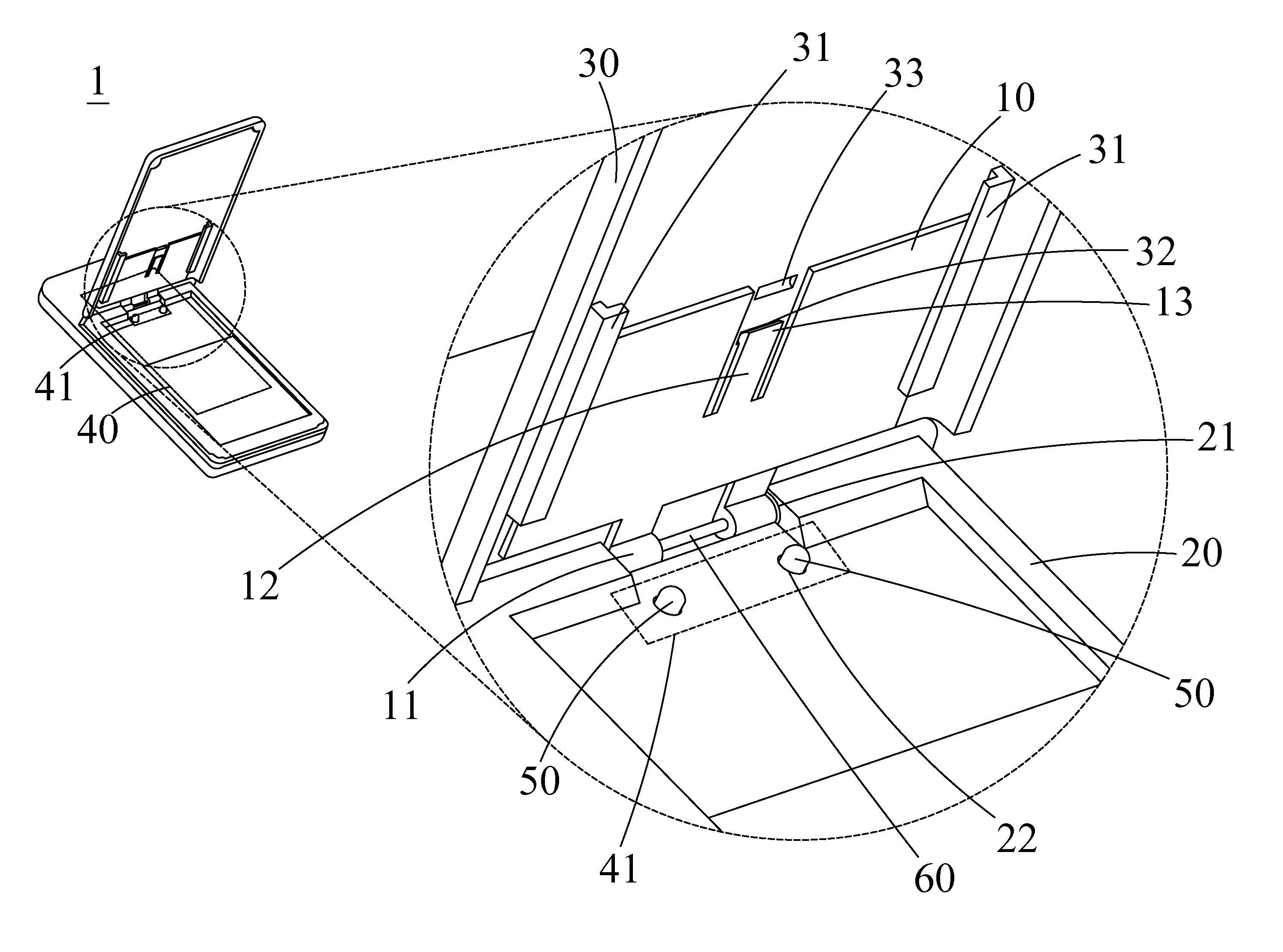
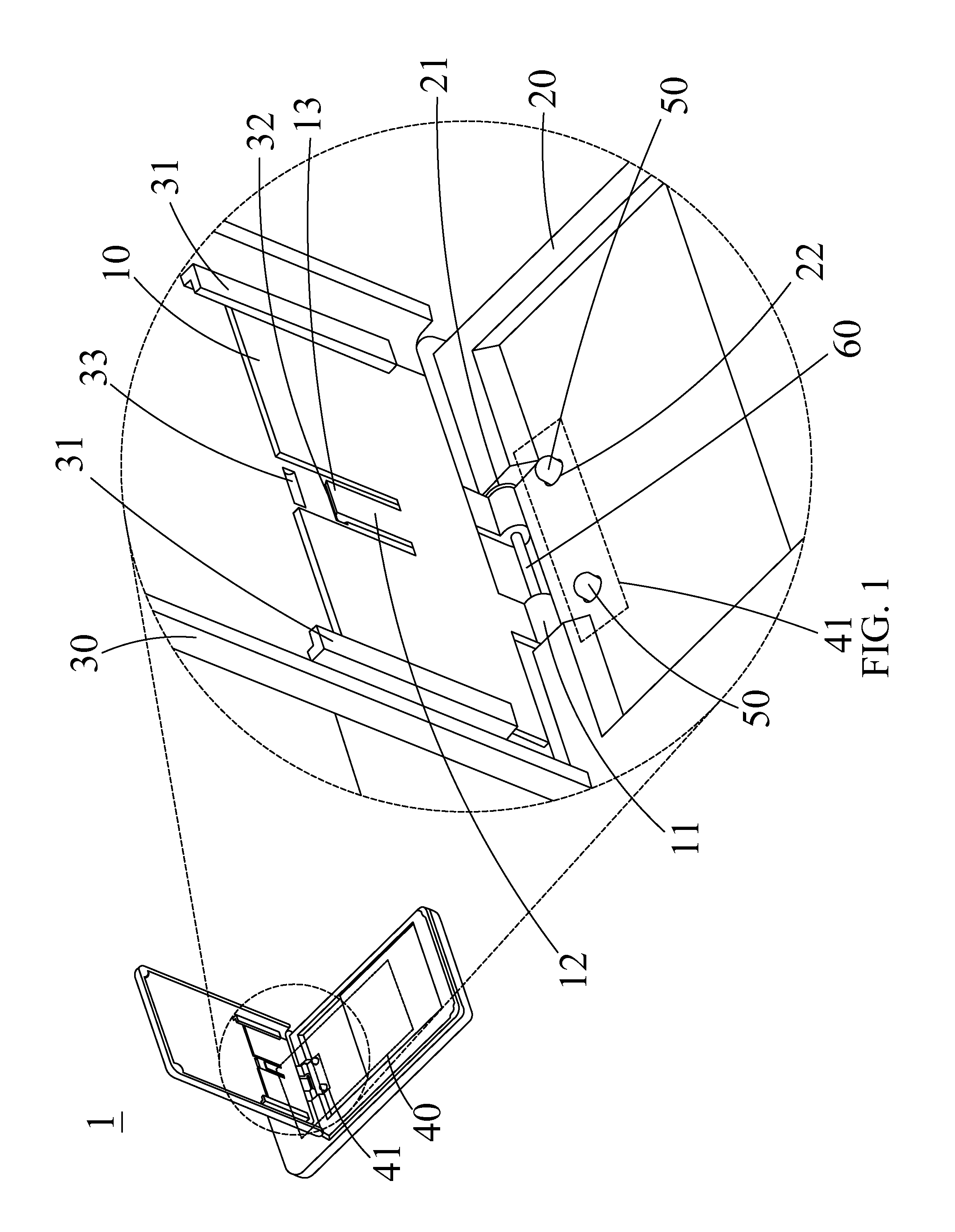
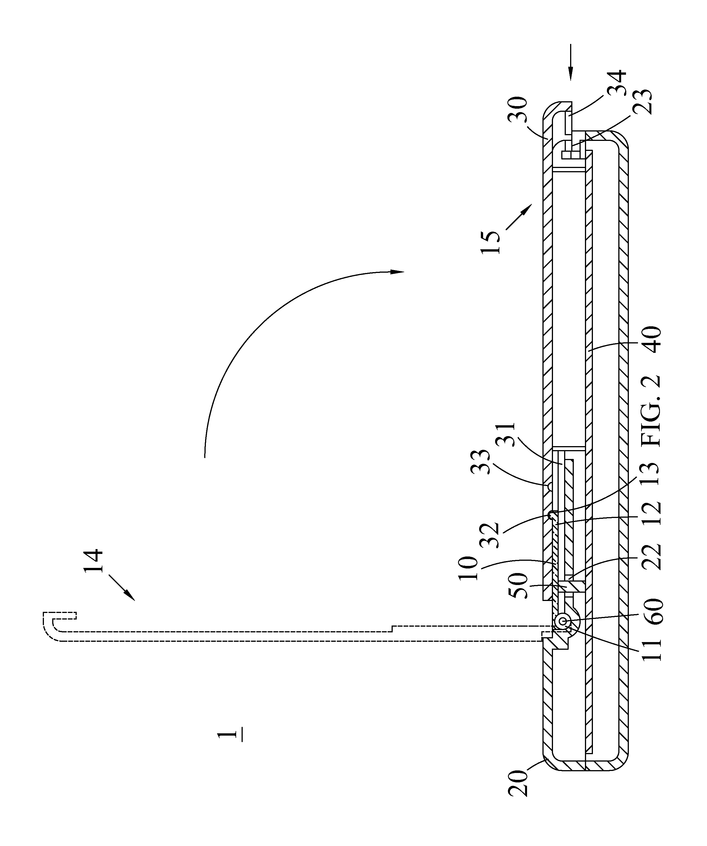
[0038]With reference to FIG. 1 ...


PUM


Abstract

An antenna spring structure and an electronic device using the same. The antenna spring structure includes an antenna spring provided with an elastic arm and a protruding portion coupled to the elastic arm, a casing having at least one opening and pivotally coupled to an end of the casing; a cover disposed on the antenna spring and having a first positioning groove and a second positioning groove formed on the protruding portion and disposed with an interval apart, a circuit board disposed inside the casing, and at least one conductive component installed on the circuit board and corresponding to at least one opening, and passed through the at least one opening and exposed from the casing. When the antenna spring is switched from a first position to a second position, the at least one conductive component presses the antenna spring.

Description

CROSS-REFERENCE TO RELATED APPLICATION[0001]This application claims the benefit of priority to China Patent Application No. 201110185272.X, filed on Jul. 4, 2011, in the State Intellectual Property Office of the People's Republic of China, the disclosure of which is incorporated herein in its entirety by reference.BACKGROUND OF THE INVENTION[0002]1. Field of the Invention[0003]The present invention relates to an antenna spring structure, in particular to the antenna spring structure applied in an electronic device and an electronic device using the same for transmitting and receiving radio signals.[0004]2. Description of the Related Art[0005]As wireless communication technology advances, various electronic devices with a wireless communication function such as mobile phones, smart phones, notebooks, computers, personal digital assistants (PDA), the global positioning system (GPS) and e-book readers are introduced. It not only makes our life convenient, but also provides a huge quant...

Claims


Application Information

Patent Timeline
Patent Type & Authority Applications(United States)
IPC IPC(8): H01Q1/24
CPCH01Q1/242H01Q1/084
Inventor LU, DING
Owner YINGHUADA (SHANGHAI) ELECTRONIC CO LTD
Why Eureka
Try Eureka