Electric connection box

a technology of electric connection box and connection box, which is applied in the direction of magnetic field measurement using galvano-magnetic devices, instruments, transportation and packaging, etc., can solve the problems of lowering the sensing performance of the current sensor b>3/b> and affecting the reliability of the product, so as to achieve space-saving design

Inactive Publication Date: 2008-01-08
YAZAKI CORP
View PDF8 Cites 17 Cited by
  • Summary
  • Abstract
  • Description
  • Claims
  • Application Information

AI Technical Summary

Benefits of technology

[0011]This invention has been made in view of the above circumstances, and an object of the invention is to provide an electric connection box in which a current sensor can be prevented from being displaced out of position, and besides the number of component parts, as well as time and labor required for an assembling operation, can be reduced, and furthermore a space-saving design can be achieved.
[0014]With this construction, it is not necessary to mount the current sensor on the lower cover, and the current sensor and the bus bar are less liable to be displaced relative to each other. And besides, the number of the component parts, as well as time and labor required for an assembling operation, is reduced. The structure is prevented from becoming complicated, and a dead area is less liable to be formed, so that the efficiency of utilization of a space is enhanced.
[0018]With this construction, the upper cover is firmly joined to the lower cover, so that the current sensor and the bus bar are still less liable to be displaced relative to each other.
[0019]In the present invention, the current sensor is molded integrally with the upper cover, and therefore the current sensor and the bus bar are less liable to be displaced relative to each other, so that a sensing performance of the current sensor is prevented from being degraded, thereby preventing the reliability from being adversely affected.
[0020]And besides, the number of the component parts, as well as the time and labor required for the assembling operation, can be reduced, and therefore the cost can be reduced, and the structure can be prevented from becoming complicated.
[0021]Furthermore, it is not necessary to beforehand secure or form a region at which the current sensor is to be mounted, and therefore the efficiency of utilization of the space is enhanced.

Problems solved by technology

As a result, the sensing performance of the current sensor 3 is lowered, and the reliability of the product is adversely affected.

Method used


Image

  • Electric connection box
  • Electric connection box
  • Electric connection box

Examples


Embodiment Construction

[0038]A preferred embodiment of the present invention will now be described in detail with reference to the drawings.

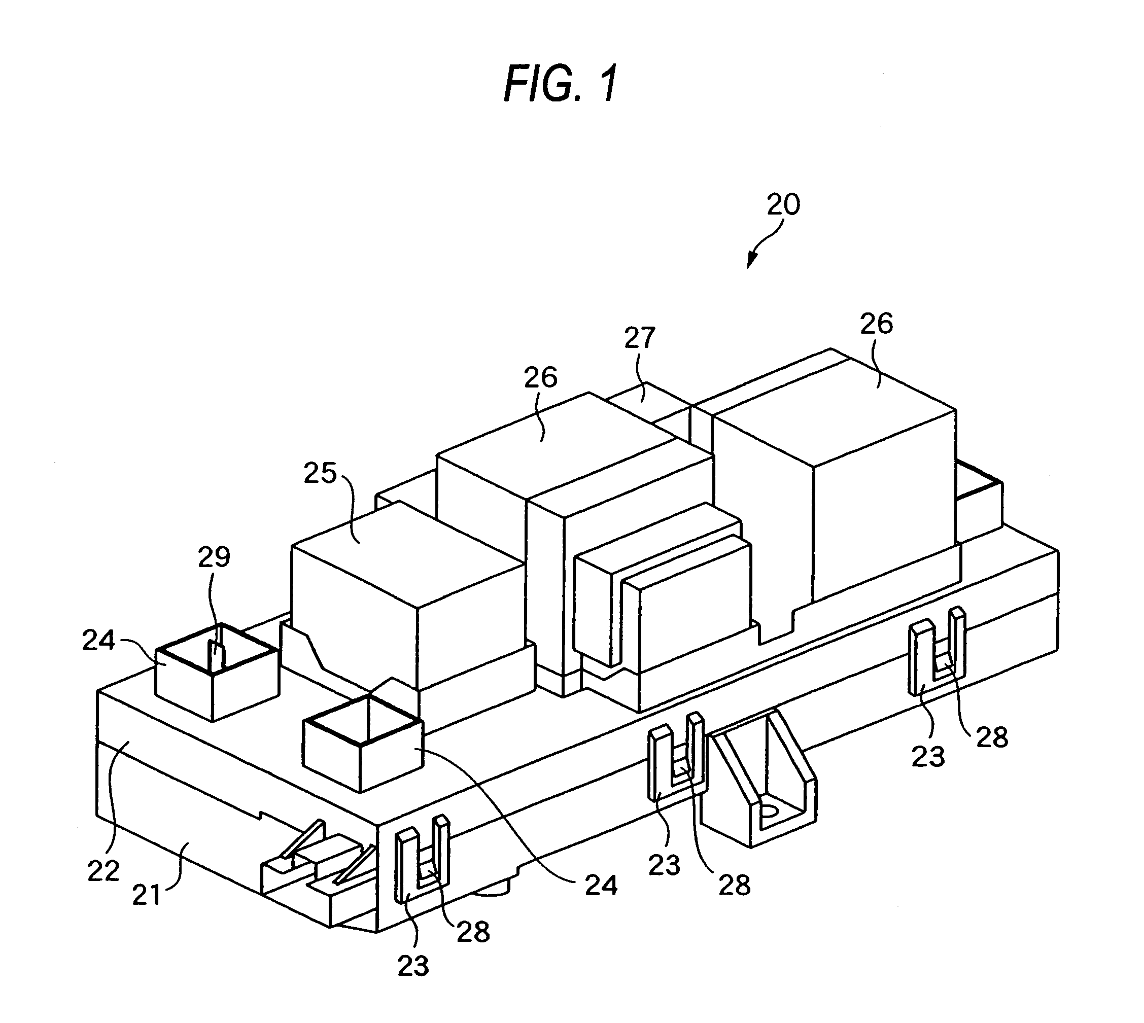
[0039]FIG. 1 is a perspective view showing one preferred embodiment of an electric connection box of the invention.

[0040]The electric connection box 20, shown in FIG. 1, is formed into a generally rectangular parallelepiped shape as a whole, and this electric connection box is mounted within an engine room having a battery (not shown) and others. The electric connection box 20 comprises a lower cover 21 and an upper cover 22 both of which are made of a synthetic resin. A receiving portion for receiving various electrical parts (described later) is formed in the inside of the electric connection box formed by the lower and upper covers 21 and 22. The electrical connection box 20 and the battery are electrically connected together by a power cable.

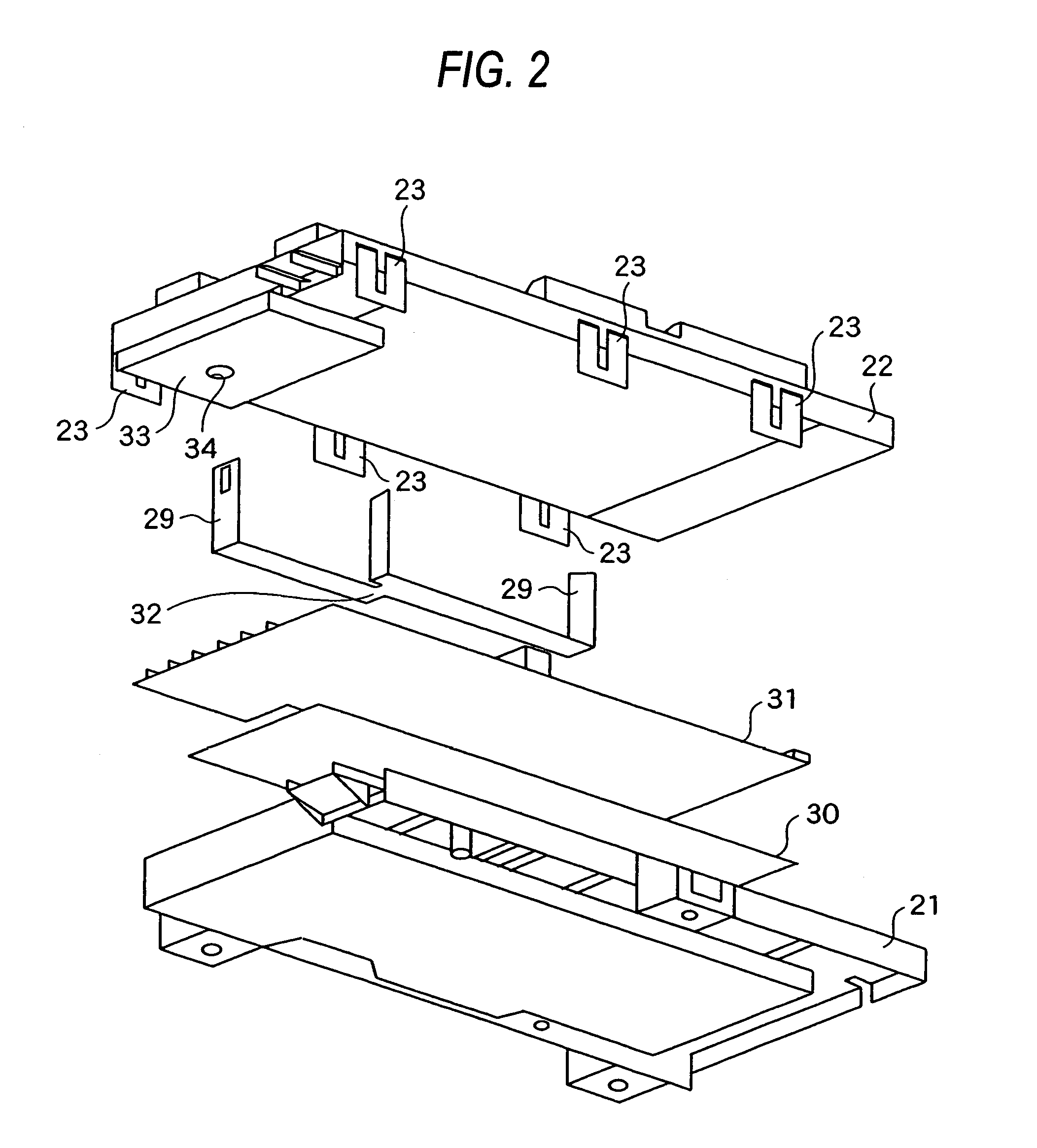
[0041]Mounting portions 35 to 37 (see FIG. 3) for the mounting of various electrical parts thereon are beforehand secured on...


PUM


Abstract

An electric connection box is mounted within an engine room of a vehicle. A bus bar and a current sensor are sequentially mounted on a lower cover, and an upper cover is joined to the lower cover to cover the bus bar and the current sensor. The current sensor is molded integrally with the upper cover. With this construction, the current sensor and the bus bar are less liable to be displaced relative to each other, and the number of the component parts, as well as time and labor required for an assembling operation, is reduced.

Description

BACKGROUND OF THE INVENTION[0001]1. Field of the Invention[0002]This invention relates to an electric connection box which has electrical parts mounted thereon, and is mounted on a vehicle or the like.[0003]2. Related Art[0004]An electric connection box and a battery are received within an engine room, for example, of an automobile in which a power source is hybridized by the addition of a motor to an engine, and the electric connection box and the battery are electrically connected together by a power cable.[0005]The electric connection box has a generally box-like shape as a whole, and as shown in FIG. 5, a bus bar 5 of an elongate rectangular plate-like shape, a current sensor 3 (which is to be electrically connected to the bus bar 5), etc., are sequentially mounted in a fitted manner on a synthetic resin-made lower cover 1, and then a synthetic resin-made upper cover 9 is put on the lower cover to cover these parts. The lower cover 1 and the upper cover 9 are fixed or fastened t...

Claims


Application Information

Patent Timeline
Patent Type & Authority Patents(United States)
IPC IPC(8): H01R12/00H05K1/00
CPCB60R16/0239Y10S439/949
Inventor SAITO, KAZUAKIIKEDA, TOMOHIROYANAGIHARA, SHINICHI
Owner YAZAKI CORP
Why Eureka
Try Eureka