Optical unit and imaging device

an optical unit and imaging device technology, applied in the field of collapsible type optical units, can solve the problems of increasing the number of parts and processes, not being economical, and the size of the external portion becomes large, so as to achieve the effect of small size, light weight and minimal optical units

Inactive Publication Date: 2006-07-13
SONY CORP
View PDF4 Cites 1 Cited by
  • Summary
  • Abstract
  • Description
  • Claims
  • Application Information

AI Technical Summary

Benefits of technology

[0041] According to the above-described optical unit, because a position-detecting means for detecting a position of the lens barrel is provided within the fixed barrel, it is possible to miniaturize the optical unit by eliminating a projection or the like on the exterior portion and to restrict an increase of the number of parts and the number of processes to its minimum.
[0042] Also, according to the image-pickup apparatus including the optical unit, since the optical unit capable of being miniaturized can be employed, it is possible to make the whole apparatus small in size and light in weight.

Problems solved by technology

Japanese Published Patent Application No. 2000-194046 (page 5, FIG. 12, etc.) However, when among the above described lens position detecting methods the former lens position detecting method according to a rotation angle of the cam ring is employed, it is necessary to arrange a projection, a switch or an electric pattern and the like on an exterior portion of the cam ring, with the result that the exterior portion becomes large in size and also the number of parts as well as the number of processes increase, which causes the problem of not being economical.
When using the latter position detecting method according to a position of the cam ring in its protruding direction, it is necessary to provide a projection on the exterior portion and also to provide a switch or a leaf spring at a predetermined position corresponding to the projection, with the result that, although the number of parts increases less than that in the former method, the exterior portion becomes bulky and against the miniaturization, which poses another problem.
For this reason, there is also posed a problem that movement efficiency of the lens to the driving force will deteriorate.

Method used


Image

  • Optical unit and imaging device
  • Optical unit and imaging device
  • Optical unit and imaging device

Examples


Embodiment Construction

[0055] Hereinafter, embodiments of a collapsible type optical unit and the image-pickup apparatus including the optical unit according to the present invention will be described with reference to the accompanying drawings.

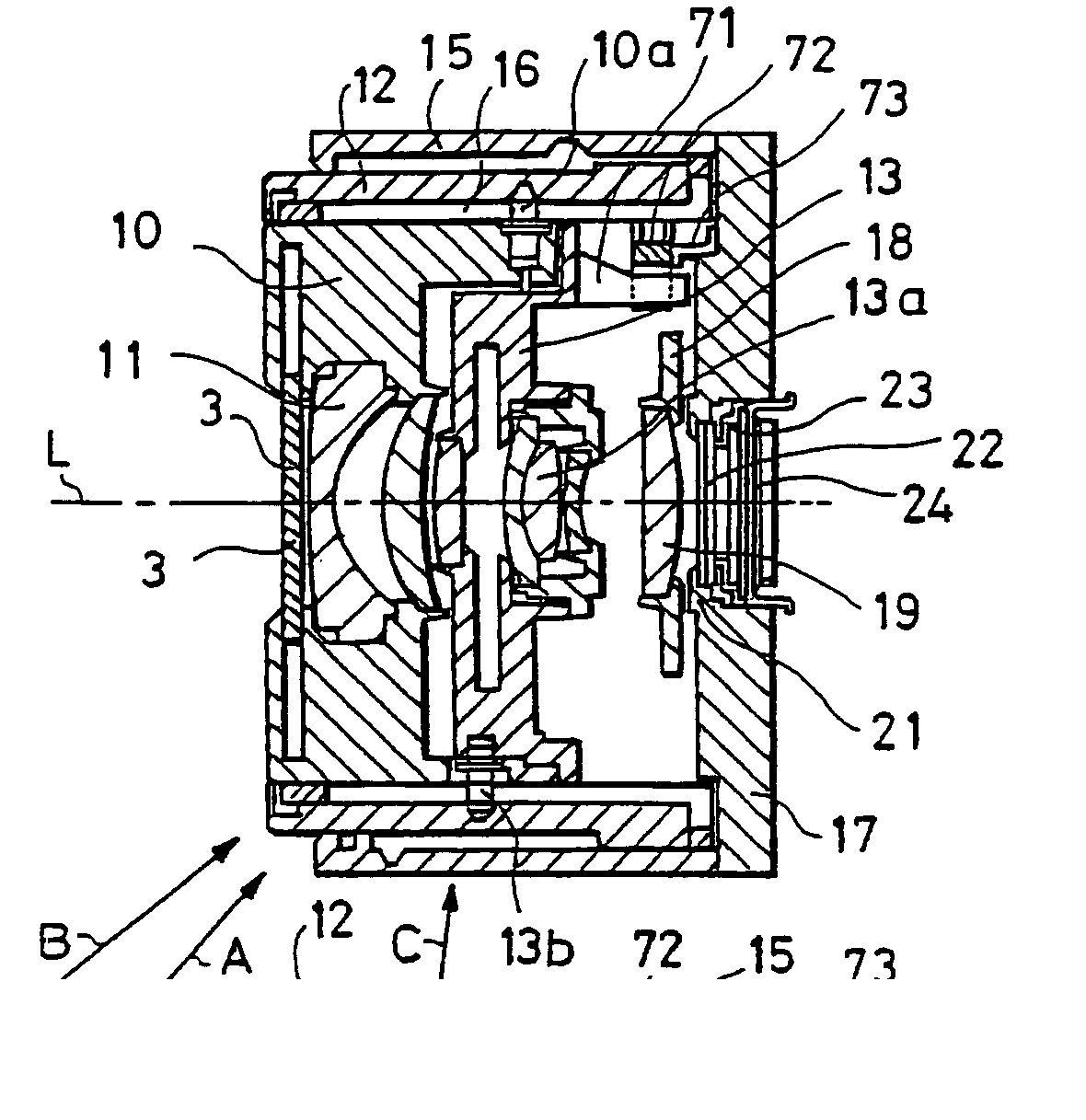
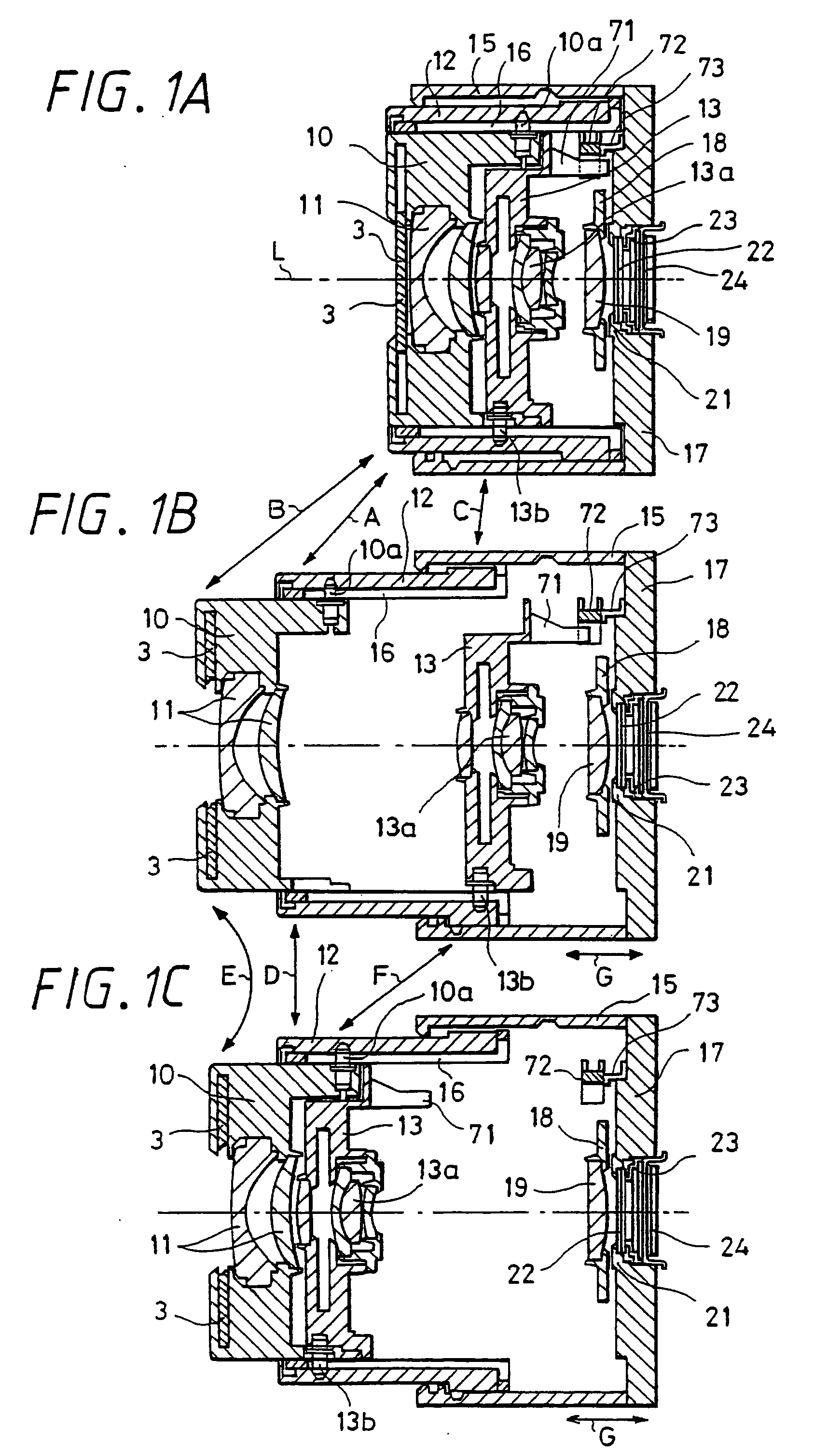
[0056]FIGS. 1A, 1B, and 1C are sectional views of a collapsible type lens according to the present invention. FIG. 1A shows a state of the collapsed position, that is, the retracted state of the lens when it is not in use; FIG. 1B shows a state of the wide angle position; FIG. 1C shows a state of the telephoto position. Note that, in FIGS. 1A, 1B, and 1C, the same parts as described in FIGS. 5A, 5B and 5C are denoted by the same symbols to be explained.

[0057] Hereupon, the zooming operation in which the first group lens frame 10 holding a plurality of lenses 11 and the second group lens frame 13 holding a plurality of lenses 13a move from the collapsed position in FIG. 1A to the wide position in FIG. 1B, and from the wide position in FIG. 1B to the telephoto posi...


PUM


Abstract

The present invention relates to a collapsible type optical unit capable of moving its optical system between a working position and a retracted position as well as an image-pickup apparatus including the optical unit. Particularly, the present invention relates to the optical unit and the image-pickup apparatus capable of acquiring lens-position information by detecting a position of a lens barrel supported to be movable with respect to a fixed barrel. The optical unit according to the present invention is a collapsible type optical unit including: a second group lens frame movable along the direction of its optical axis with respect to a fixed ring and a rear barrel, and a solid-state image-pickup device provided behind the second group lens frame, in which on the movable second group lens frame, a position-detecting means for detecting a position of the second group lens frame is provided. According to the present invention, projection and the like on the exterior portion can be eliminated to be small in size and an increase of the number of parts and the number of processes can be restricted to the minimum.

Description

TECHNICAL FIELD [0001] The present invention relates to a collapsible type optical unit in which an optical system is movable between a working position and a retracted position, as well as an image-pickup apparatus including the optical unit such as a digital still camera and a digital video camera; and particularly relates to the optical unit and the image-pickup apparatus including the optical unit capable of acquiring information on a lens position (information, for example, on a zoom position) by detecting a position of a lens barrel supported to be movable with respect to a fixed barrel. BACKGROUND ART [0002] In recent years, the improvement in portability and operability has been demanded for the image-pickup apparatus such as a digital still camera and a digital video camera. The whole camera is now required to be small-sized and the miniaturization of an optical system such as a lens and a lens barrel employed in the image-pickup apparatus has been in progress. In addition,...

Claims


Application Information

Patent Timeline
Patent Type & Authority Applications(United States)
IPC IPC(8): G03B17/00G02B7/04G02B7/08
CPCG02B7/08G03B5/04G03B17/12
Inventor IMAI, SATOSHIAOKI, NOBUAKIMAKII, TATSUOYAMAOKA, HIDEKI
Owner SONY CORP
Why Eureka
Try Eureka