Inductor layout having improved isolation through blocking of coupling between inductors, and integrated circuit device using same

a technology of inductors and layouts, applied in the direction of transformers/inductances, inductances, inductances, etc., can solve the problems of old magnetic field coupling between inductors, the problem of magnetic field coupling mainly through the substrate, and the practical problem of magnetic coupling, etc., to reduce the area of the ic device, reduce the cost competitiveness of the ic, and miniaturize the chip

Inactive Publication Date: 2019-06-13
KOREA ADVANCED INST OF SCI & TECH +1
View PDF0 Cites 1 Cited by
  • Summary
  • Abstract
  • Description
  • Claims
  • Application Information

AI Technical Summary

Benefits of technology

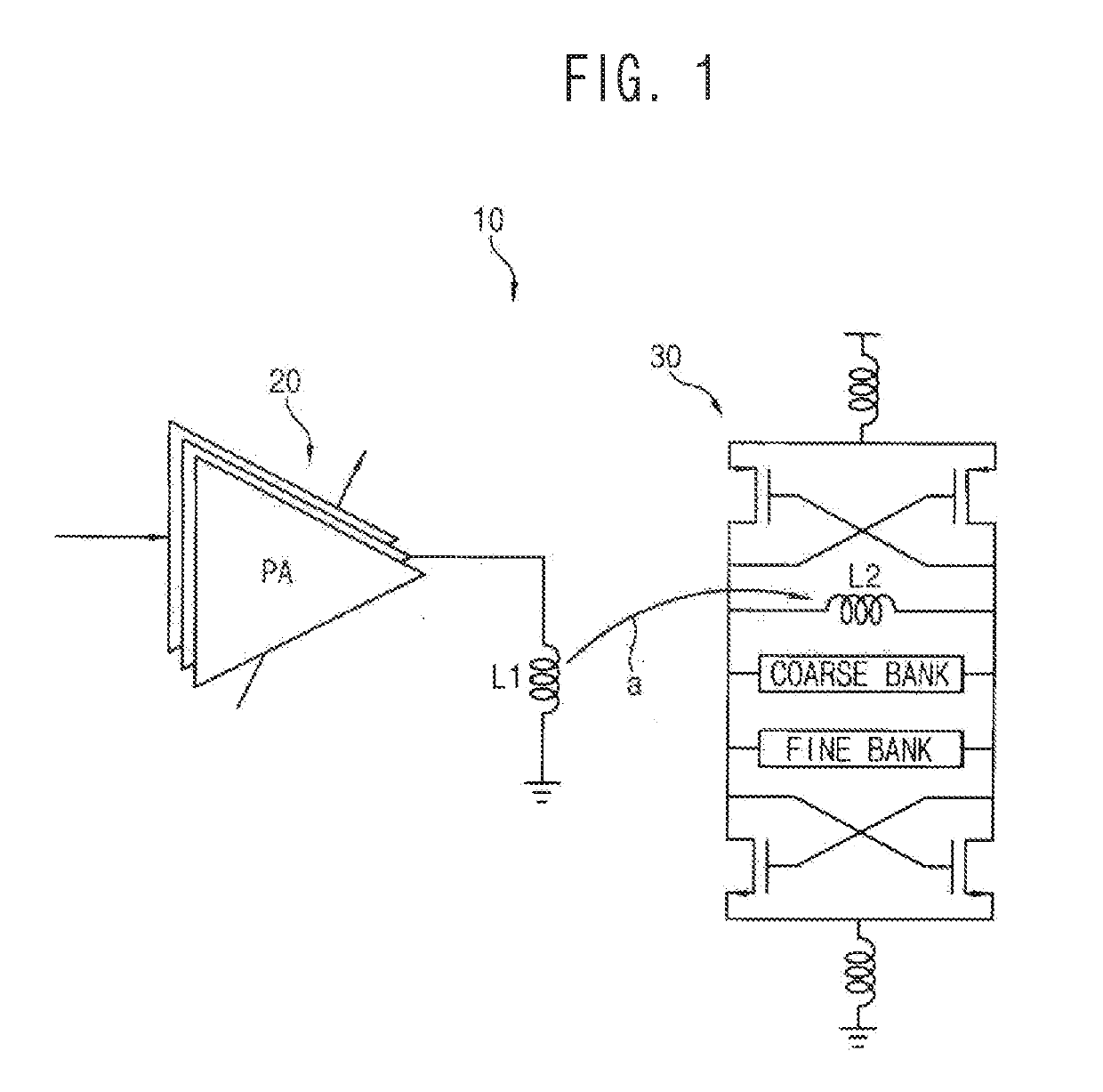
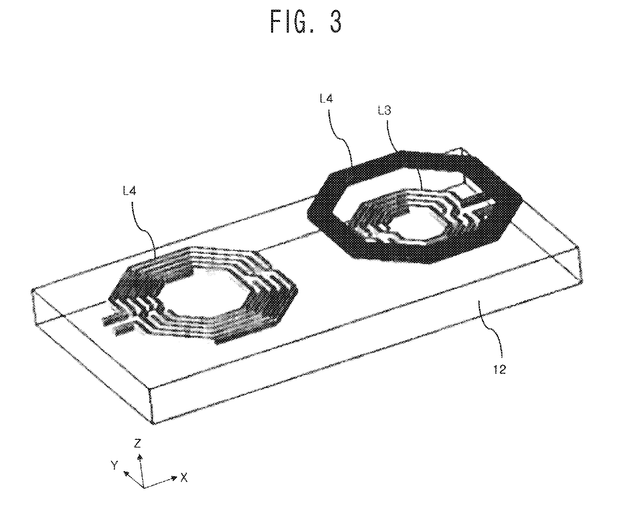
[0017]Thus, in a small IC device constituting a wireless transmitter, a wireless receiver, or a wireless transceiver, disposing the conductor loop for shielding the magnetic coupling over the inductors can protect the inductors from being interfered with the external magnetic field by shielding the magnetic field coupling between the inductors.
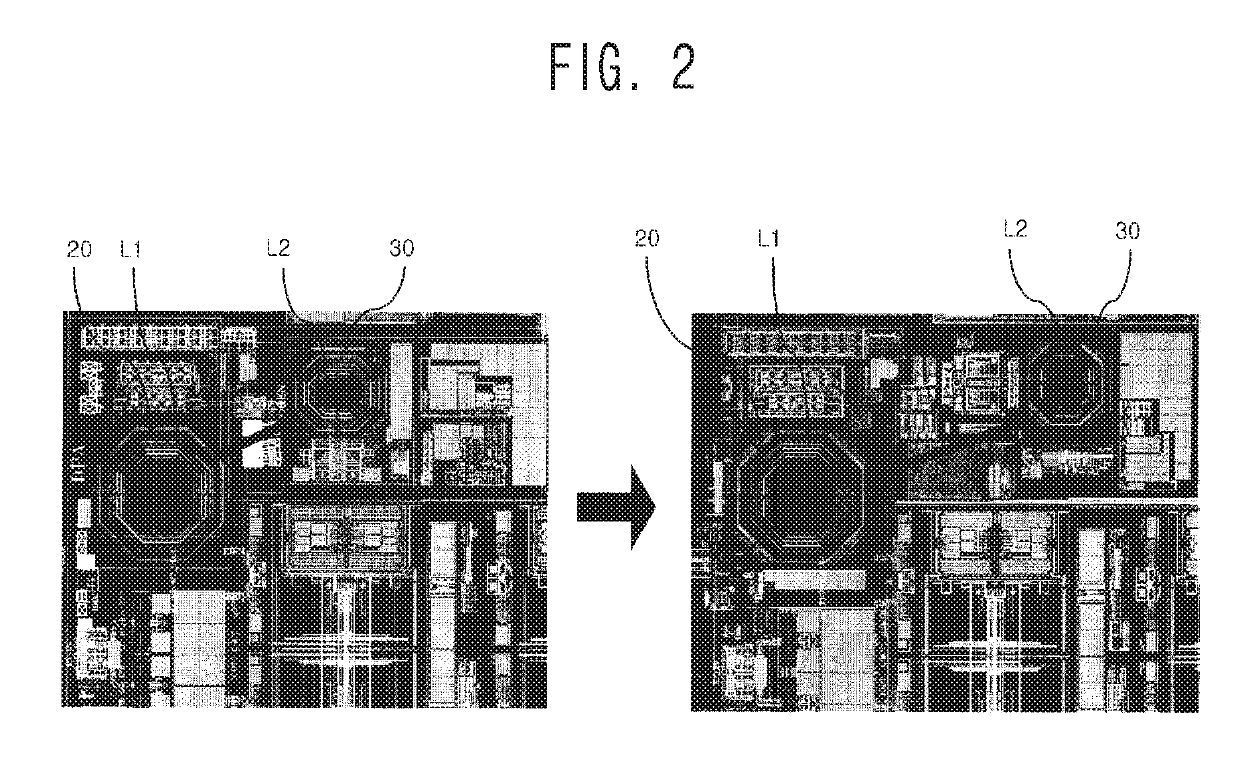
[0018]According to the present invention, the inductors can be disposed closer to each other while the degree of magnetic coupling per unit separation distance between the inductors is kept the same as the conventional one. Therefore, it is possible to reduce the area of the IC device such as an RFIC chip employing such an inductor layout, and to miniaturize a chip. Since the inductors are freed from the magnetic field coupling and can be arranged closer to each other than the conventional method, the cost competitiveness of the IC (for example, the RFIC chip) chip installed with the inductors together can be increased.
[0019]Also, according to the present invention, when the inductors are arranged at the same distance as the conventional ones, the amount of magnetic field coupling is greatly reduced compared with the conventional one, and thus an inductor-mounted IC with superior performance can be realized. In another aspect, an IC (e.g., an RFIC chip) that is competitive in terms of performance can be implemented because it is possible to integrate a calibration circuit or other circuits that can increase reliability by reducing wasted space.

Problems solved by technology

For RFICs, which are used primarily in radar and wireless communications, an issue of magnetic field coupling between inductors is an old problem.
The magnetic field coupling mainly through the substrate has been a problem, and a lot of researches on the issue have been carried out.
As a result, the magnetic coupling issue became a practical problem.
However, as an area of the RFIC becomes smaller, the distance between blocks of the RFIC becomes closer, and an issue of isolation between them newly emerges.
That is, since the distance between the inductors provided in each block is getting closer, the magnetic coupling issue between the inductors is further accelerated.
In addition, not only conventional voltage controlled oscillators (VCOs) but also digitally controlled oscillators (DCOs), which are actively used recently, have the problem of magnetic coupling between inductors.

Method used


Image

  • Inductor layout having improved isolation through blocking of coupling between inductors, and integrated circuit device using same
  • Inductor layout having improved isolation through blocking of coupling between inductors, and integrated circuit device using same
  • Inductor layout having improved isolation through blocking of coupling between inductors, and integrated circuit device using same

Examples


Embodiment Construction

[0029]The specific structural and functional descriptions of the embodiments of the present inventive concept disclosed herein are merely illustrative for the purpose of describing embodiments of the present inventive concept. Embodiments of the present inventive concept may be embodied in various forms and should not be construed as limited to the embodiments set forth herein.

[0030]The present inventive concept can be variously modified and can take various forms. Specific embodiments are illustrated in the drawings and described in detail herein. It should be understood, however, that the present inventive concept is not intended to be limited to the particular forms disclosed, but includes all modifications, equivalents, and alternatives falling within the spirit and scope of the present inventive concept.

[0031]It will be understood that, although the terms first, second, third etc. may be used herein to describe various elements, these elements should not be limited by these ter...


PUM

PropertyMeasurementUnit
magnetic latitudeaaaaaaaaaa
magnetic fieldaaaaaaaaaa
magnetic fluxaaaaaaaaaa

Abstract

Disclosed are an inductor layout and an integrated circuit device with improved isolation between inductors through shielding magnetic coupling between the inductors. first and second inductor coils are horizontally spaced apart from each other. A conductor loop is disposed in parallel above the first inductor coil and shields magnetic coupling between the first and second inductor coils in the manner that a part of magnetic flux of a first time-varying magnetic field generated by the second inductor coil is cancelled by magnetic flux of a second magnetic field generated by an induction current that flows in the conductor loop magnetically interlinked with the first time-varying magnetic field. The inductor layout can be applied to an RFIC device to reduce magnetic coupling between inductors of a power amplifier and an oscillator. Improved performance of the device and a very small RFIC can be achieved.

Description

CROSS-REFERENCE TO RELATED APPLICATION[0001]This application claims priority under 35 USC § 119 to Korean Patent Application No. 10-2016-0068260, filed on Jun. 1, 2016 in the Korean Intellectual Property Office (KIPO), the contents of which are herein incorporated by reference in their entirety.BACKGROUND1. Technical Field[0002]The present invention relates to a technology for reducing coupling between magnetic inductors to improve isolation therebetween, and more particularly, to a technology for protecting an inductor from an external magnetic field in a small integrated circuit (IC) device, such as a radio frequency integrated circuit (RFIC), including an inductor, thereby miniaturizing the IC device as well as improving signal processing performance of the IC device.2. Description of the Related Art[0003]For RFICs, which are used primarily in radar and wireless communications, an issue of magnetic field coupling between inductors is an old problem. The magnetic field coupling ma...

Claims


Application Information

Patent Timeline
Patent Type & Authority Applications(United States)
IPC IPC(8): H01F27/36H01F27/28H04B5/00H01F38/14H01L23/522H01L49/02
CPCH01F27/365H01F27/2804H04B5/0075H01F38/14H01L23/5227H01L28/10H01F27/38H03F1/34H01F17/0006H01F27/289H01F2017/008H03B5/1228H03B5/1215H03B5/1265H03F3/195H03F1/565H01F27/363H01F27/36
Inventor YOO, HYUNG-JOUNYOO, SANG-SUNLEE, KANG-YOON
Owner KOREA ADVANCED INST OF SCI & TECH
Why Eureka
Try Eureka