
Capacitive touch screen and manufacturing method thereof

Inactive Publication Date: 2012-03-15
SAMSUNG ELECTRO MECHANICS CO LTD
View PDF1 Cites 11 Cited by
  • Summary
  • Abstract
  • Description
  • Claims
  • Application Information

AI Technical Summary

Benefits of technology

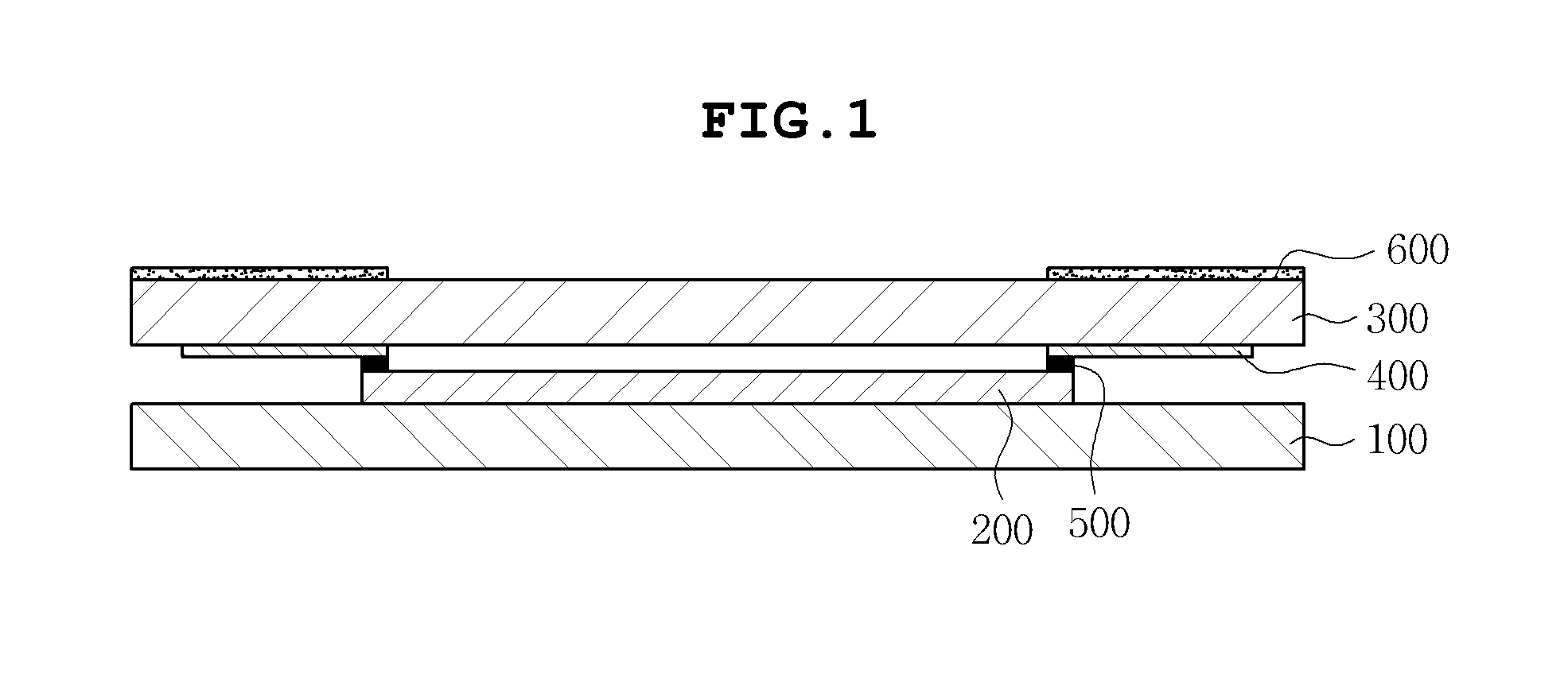
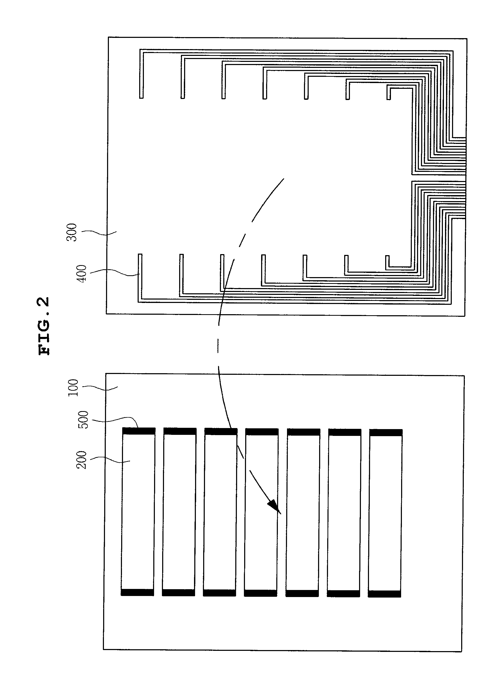
[0013]The present invention has been made in an effort to provide a capacitive touch screen capable of increasing a degree of freedom in terms of a design and preventing defects of electrode wirings and electrode patterns by disposing the electrode patterns and the electrode wirings on different planes.
[0014]Further, the present invention has been made in an effort to provide a method of manufacturing a capacitive touch screen capable of manufacturing a touch screen without causing defects of electrode patterns during the formation of electrode wirings by forming electrode patterns on a base member and the electrode wiring on a window and then conducting between the electrode patterns and the electrode wirings.

Problems solved by technology

The capacitive touch screen according to the prior art separately configures the upper substrate and the lower substrate to form the electrode patterns and the electrode wirings, such that there is a problem in that the configuration of the touch screen becomes complicated.
However, the single layer capacitive touch screen according to the prior art has a complicated structure since the electrode patterns and the electrode wirings are formed on the same plane, thereby causing the short problem between the electrode wirings.
Further, the single-layer capacitive touch screen according to the prior art causes several problems during the manufacturing process.
Since the electrode patterns and the electrode wirings are formed on the same member, when the electrode wirings are formed after the electrode patterns are formed, the electrode patterns may be damaged or the electrode wirings may be damaged.
In particular, when the electrode pattern is made of a conductive polymer and the etching process or the heat treatment process is performed during a process of forming an electrode wiring, there is a problem in that the sheet resistance of the electrode pattern is changed due to the modification of the conductive polymer.

Method used


Image

  • Capacitive touch screen and manufacturing method thereof
  • Capacitive touch screen and manufacturing method thereof
  • Capacitive touch screen and manufacturing method thereof

Examples


Embodiment Construction

[0034]Various objects, advantages and features of the invention will become apparent from the following description of embodiments with reference to the accompanying drawings.

[0035]The terms and words used in the present specification and claims should not be interpreted as being limited to typical meanings or dictionary definitions, but should be interpreted as having meanings and concepts relevant to the technical scope of the present invention based on the rule according to which an inventor can appropriately define the concept of the term to describe most appropriately the best method he or she knows for carrying out the invention.

[0036]The above and other objects, features and advantages of the present invention will be more clearly understood from the following detailed description taken in conjunction with the accompanying drawings. In the specification, in adding reference numerals to components throughout the drawings, it is to be noted that like reference numerals designat...


PUM

PropertyMeasurementUnit
Electrical conductoraaaaaaaaaa

Abstract

Disclosed herein are a capacitive touch screen and a manufacturing method thereof. The capacitive touch screen includes a base member on which a plurality of electrode patterns are formed; a conductive adhesive member formed on ends of the electrode patterns; and a window disposed on an upper side of the base member and having a plurality of electrode wirings formed in the outer side thereof to be conducted with the electrode patterns by the conductive adhesive member and to be opposite to the electrode patterns.

Description

CROSS REFERENCE TO RELATED APPLICATION[0001]This application claims the benefit of Korean Patent Application No. 10-2010-0089433, filed on Sept. 13, 2010, entitled “Capacitive Touch Screen And Manufacturing Method Thereof”, which is hereby incorporated by reference in its entirety into this application.BACKGROUND OF THE INVENTION[0002]1. Technical Field[0003]The present invention relates to a capacitive touch screen and a manufacturing method thereof.[0004]2. Description of the Prior Art[0005]With the development of a mobile communication technology, user terminals such as cellular phones, PDAs, and navigations can serve as a display unit that simply displays character information as well as a unit for providing various and complex multi-media such as audio, moving picture, radio internet web browser, etc. Due to a recent demand for a larger display screen within a terminal having a limited size, a display scheme adopting a touch screen has been more in the limelight. The touch scre...

Claims


Application Information

Patent Timeline
IPC IPC(8): G06F3/045H05K3/00
CPCG06F3/044Y10T29/49124G06F2203/04103G06F2203/04111G06F3/04164G06F3/0443G06F3/0446
Inventor KIM, WOON CHUNOH, YONG SOOLEE, JONG YOUNG
Owner SAMSUNG ELECTRO MECHANICS CO LTD
Learn More