Supercharge Your Innovation With Domain-Expert AI Agents!

Liquid ejecting apparatus

a technology of liquid ejecting apparatus and liquid ejector, which is applied in printing and other directions, can solve the problems of ink soiled paper in contact with hydrophilic portion,

Inactive Publication Date: 2018-08-09
SEIKO EPSON CORP
View PDF2 Cites 2 Cited by
  • Summary
  • Abstract
  • Description
  • Claims
  • Application Information

AI Technical Summary

Benefits of technology

The invention provides a liquid ejecting apparatus that prevents liquid from adhering to the surface it is ejected onto. This is achieved by creating a liquid repellent surface on the front end surface of the liquid ejecting head where liquid droplets are ejected. A lyophilic surface is also created on the upstream surface, which has a higher affinity for liquid than the liquid repellent surface. These surfaces work together to prevent liquid from spreading or sticking to the surface, resulting in a better quality liquid ejected image.

Problems solved by technology

Because ink that has adhered to the ejection surface accumulates at the hydrophilic portion, the paper in contact with the hydrophilic portion may become soiled with ink.

Method used


Image

  • Liquid ejecting apparatus
  • Liquid ejecting apparatus
  • Liquid ejecting apparatus

Examples


Embodiment Construction

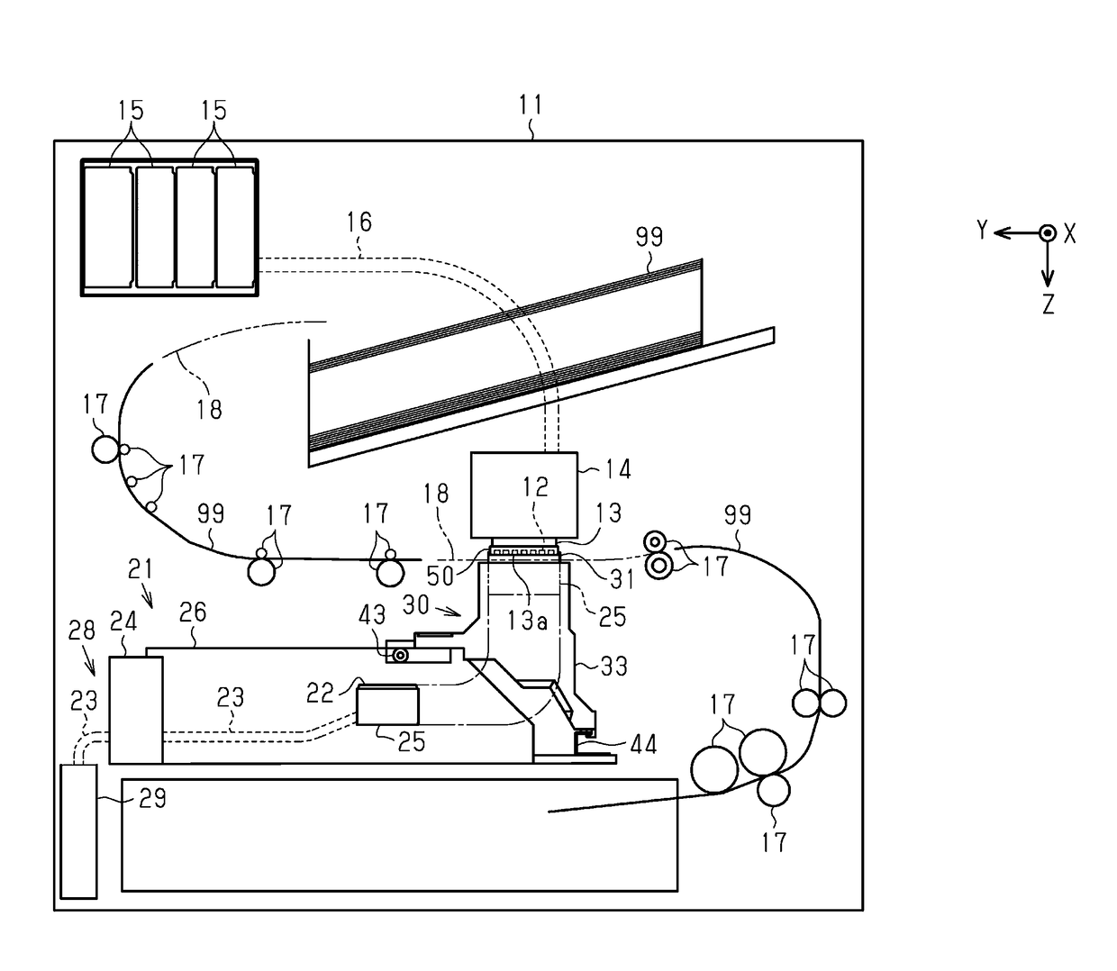
[0018]Hereinafter, an embodiment of the invention will be described with reference to the accompanying drawings. The liquid ejecting apparatus is an ink jet printer that performs recording (printing) by ejecting ink, which is an example of a liquid, onto a medium such as paper.

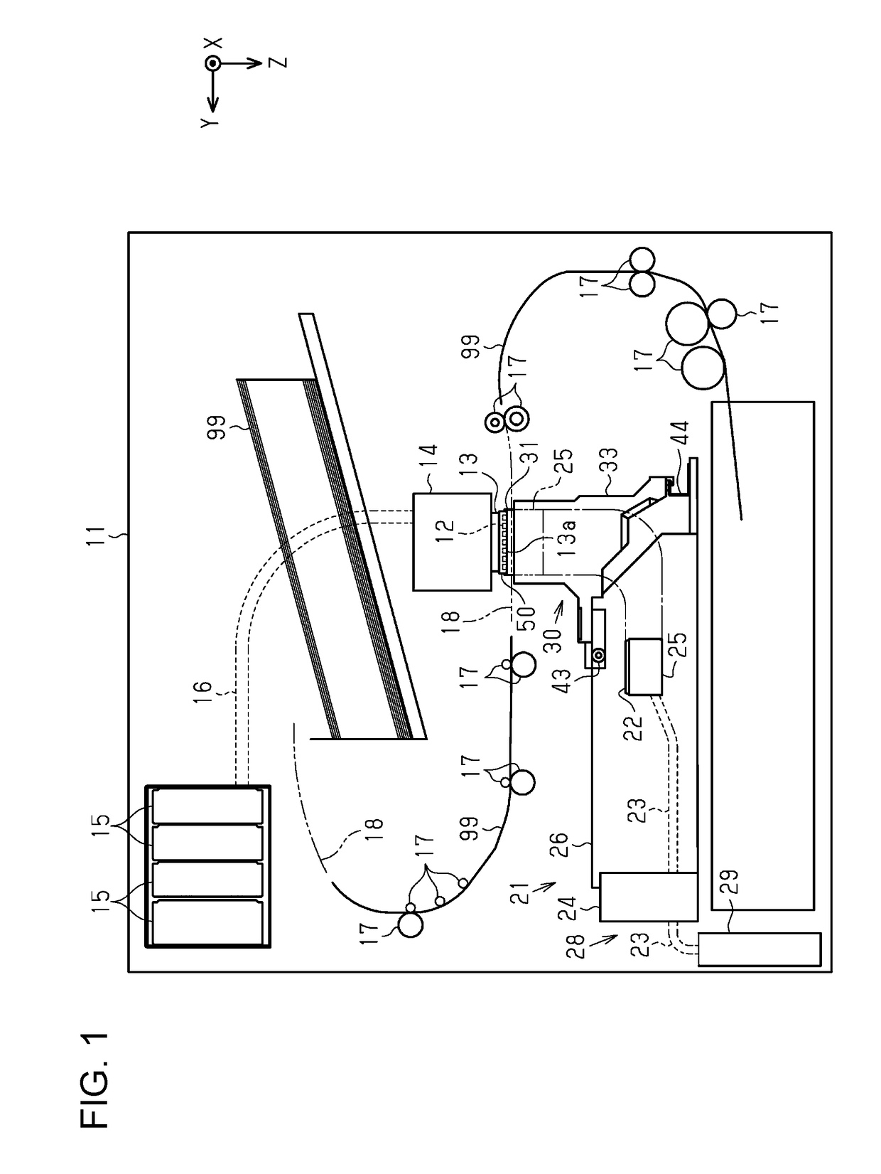
[0019]As illustrated in FIG. 1, a liquid ejecting apparatus 11 includes a liquid ejecting head 13, a holding unit 14 that holds the liquid ejecting head 13, a supply channel 16 disposed so as to supply liquid of liquid supply sources 15 toward the liquid ejecting head 13, and a plurality of transport rollers 17 disposed along a transport path 18 of a medium 99. The liquid supply sources 15 are, for example, cartridge-type liquid containers detachably mounted on the liquid ejecting apparatus 11. The liquid supply sources 15 may be a liquid tank that the liquid ejecting apparatus 11 is equipped with. The liquid tank may be formed so as to be exchangeable and so as to be capable of injecting a liquid.

[0020]The po...


PUM


Abstract

A liquid ejecting apparatus includes a liquid ejecting head including a front end surface, an upstream surface that intersects with the front end surface, and a nozzle that opens at the front end surface, the liquid ejecting head being configured to eject liquid from the nozzle, and a wiping member configured to wipe the front end surface in a wiping direction. The upstream surface is located upstream of the front end surface in the wiping direction. A liquid repellent surface that repels the liquid is provided in a portion of the front end surface where the nozzle opens. A lyophilic surface having a higher affinity for the liquid than the liquid repellent surface is provided on the upstream surface and the front end surface. A portion of the lyophilic surface on the upstream surface is connected to a portion of the lyophilic surface on the front end surface.

Description

BACKGROUND1. Technical Field[0001]The present invention relates to a liquid ejecting apparatus such as a printer.2. Related Art[0002]As an example of a liquid ejecting apparatus, there is an ink jet recording apparatus that is provided with, in an ejection surface thereof, a concave portion that forms a hydrophilic portion around a water repellent surface that serves as a water repellent surface around nozzle rows so as to improve the ease of cleaning of the ejection surface (for example, JP-A-2007-253537).[0003]Because ink that has adhered to the ejection surface accumulates at the hydrophilic portion, the paper in contact with the hydrophilic portion may become soiled with ink.SUMMARY[0004]An advantage of some aspects of the invention is that a liquid ejecting apparatus in which a liquid does not tend to adhere to a medium is provided.[0005]A liquid ejecting apparatus according to an aspect of the invention includes a liquid ejecting head including a front end surface, an upstream...

Claims


Application Information

Patent Timeline
Patent Type & Authority Applications(United States)
IPC IPC(8): B41J2/165
CPCB41J2/16535B41J2/16505B41J2/16517B41J2/16538
Inventor TAKANASHI, HIROMICHI
Owner SEIKO EPSON CORP
Features
  • R&D
  • Intellectual Property
  • Life Sciences
  • Materials
  • Tech Scout
  • Unparalleled Data Quality
  • Higher Quality Content
  • 60% Fewer Hallucinations
Learn More