Multi-lens optical device

a multi-lens optical device and optical device technology, applied in the field of optical devices, can solve the problems of increasing the fabricating cost of the panoramic optical device, the mobile phone cannot adopt the operating principle of the ricoh panoramic optical device to capture the panoramic image, and the mobile phone cannot rotate along, so as to achieve cost-effectiveness, simple transmitting task, and sufficient computing capability

Inactive Publication Date: 2018-09-20
PRIMAX ELECTRONICS LTD
View PDF4 Cites 3 Cited by
  • Summary
  • Abstract
  • Description
  • Claims
  • Application Information

AI Technical Summary

Benefits of technology

[0009]From the above descriptions, the multi-lens optical device of the present invention is only equipped with plural optical modules, the storage element and the controlling unit. Moreover, the pixel correction table is stored in the storage element. The multi-lens optical device is responsible for the task of capturing the local images and the simple transmitting task. Especially, the strenuous image processing task is performed by the image processing module of the electronic device. Generally, the mobile phone or the comparable electronic device carried by the user can provide sufficient computing capability to the image processing module. The multi-lens optical device of the present invention has the function capturing panoramic image. Moreover, the multi-lens optical device of the present invention is cost-effective. Consequently, the drawbacks of the conventional technologies can be effectively overcome.

Problems solved by technology

In other words, the smart phone cannot adopt the operating principle of the RICOH panoramic optical device to capture the panoramic images.
However, since it is difficult to rotate the mobile phone along the horizontal direction at the constant speed, the local images of the panoramic image usually have different widths.
However, the highly-technical program increases the fabricating cost of the panoramic optical device.

Method used


Image

  • Multi-lens optical device
  • Multi-lens optical device
  • Multi-lens optical device

Examples


Embodiment Construction

[0018]For overcoming the drawbacks of the conventional technologies, the present invention provides a multi-lens optical device. First of all, the structure of the multi-lens optical device will be illustrated as follows.

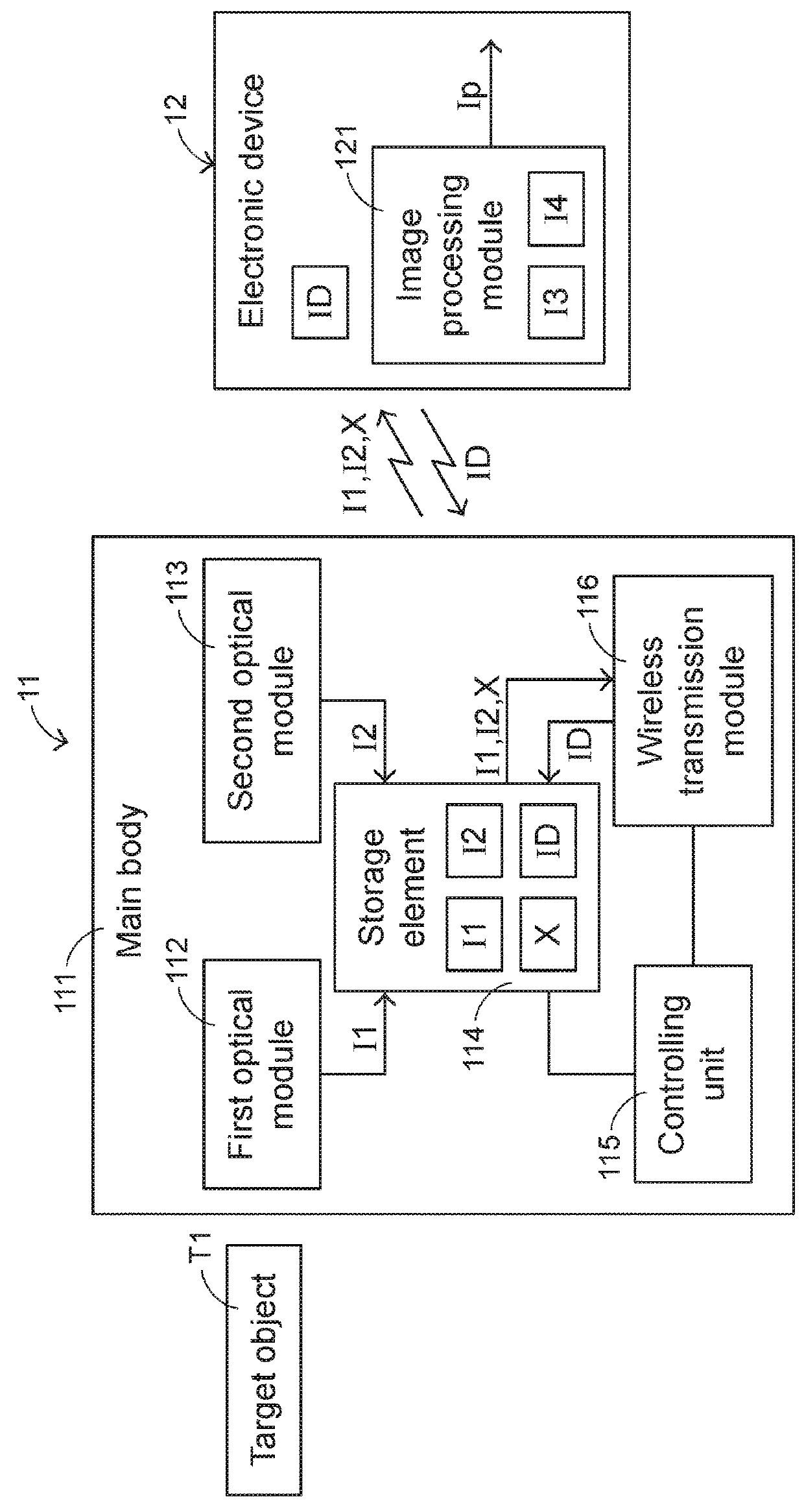
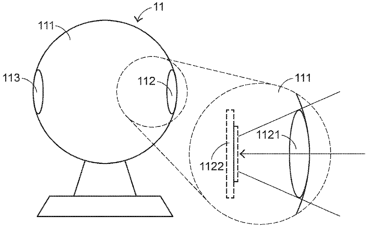
[0019]Please refer to FIGS. 1 and 2. FIG. 1 is a schematic functional block diagram illustrating the relationship between a multi-lens optical device of a first embodiment and an electronic device. FIG. 2 is a schematic side view illustrating the multi-lens optical device according to the first embodiment of the present invention. In FIG. 1, the multi-lens optical device 11 and the electronic device 12 are shown. The multi-lens optical device 11 is in wireless connection with the electronic device 12. In an embodiment, the multi-lens optical device 11 comprises a main body 111, a first optical module 112, a second optical module 113, a storage element 114, a controlling unit 115 and a wireless transmission module 116. The first optical module 112 is located at a fir...


PUM


Abstract

A multi-lens optical device is in communication with an electronic device. The multi-lens optical device includes plural optical modules and a storage element. A pixel correction table is stored in the storage element. The plural optical modules shoot the scene to acquire plural images. The plural images and the pixel correction table are transmitted from the multi-lens optical device to the electronic device. The electronic device produces a panoramic image according to the plural images and the pixel correction table. The multi-lens optical device is responsible for the task of capturing the local images and the simple transmitting task. The image processing task is performed by the electronic device. Consequently, the cost of the multi-lens optical device is reduced.

Description

FIELD OF THE INVENTION[0001]The present invention relates to an optical device, and more particularly to an optical device with the function of capturing panoramic images.BACKGROUND OF THE INVENTION[0002]With development of electronic industries and advance of industrial technologies, various electronic devices are designed toward small size, light weightiness and easy portability. Consequently, these electronic devices can be applied to mobile business, entertainment or leisure purposes whenever or wherever the users are. For example, various image pickup devices are widely used in many kinds of fields such as smart phones, tablet computers, wearable electronic devices or any other appropriate portable electronic devices. Since the electronic devices are small and portable, users can take the electronic devices to capture images and store the images according to the users' requirements.[0003]Recently, a portable electronic device with the function of capturing panoramic images has ...

Claims


Application Information

Patent Timeline
Patent Type & Authority Applications(United States)
IPC IPC(8): H04N5/232G02B13/06G06T5/50G06T5/00
CPCH04N5/23238G06T5/006G06T5/50G02B13/06H04N23/55H04N23/80G03B37/04G03B2206/00H04N5/2628H04N23/698
Inventor PAI, NIEN-HUA
Owner PRIMAX ELECTRONICS LTD
Why Eureka
Try Eureka