Synchronous Machine Module, Vehicle Drive and Vehicle

a technology of synchronous machine and module, applied in the direction of machines/engines, starter details, electric generator control, etc., can solve the problems of preventing successful purely controlled run-up, requiring additional equipment, and requiring high cost and sensitive electronics. achieve the effect of simple and robus

a technology of synchronous machine and module, applied in the direction of machines/engines, starter details, electric generator control, etc., can solve the problems of preventing successful purely controlled run-up, requiring additional equipment, and requiring high cost and sensitive electronics. achieve the effect of simple and robus

US20180278184A1Active Publication Date: 2018-09-27ROLLS ROYCE DEUT LTD & CO KG

Image

  • Synchronous Machine Module, Vehicle Drive and Vehicle
  • Synchronous Machine Module, Vehicle Drive and Vehicle

Examples


Embodiment Construction

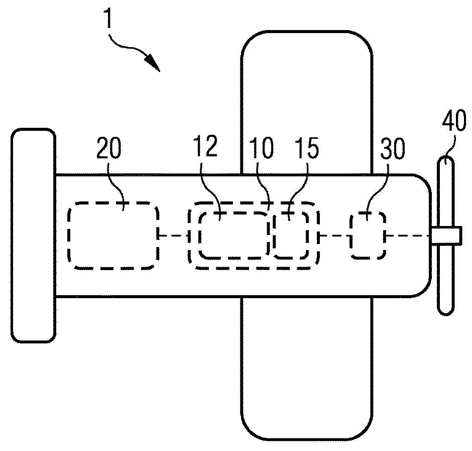
[0029]The vehicle according to the embodiment illustrated in FIG. 1 is a hybrid-electric aircraft 1.

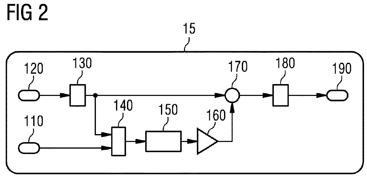
[0030]The hybrid-electric aircraft 1 has a hybrid-electric drive, which includes a synchronous machine module 10 having a permanent-magnet synchronous machine 12 and a rotational speed controller 15 as described below. An internal combustion engine 20 is connected to the drive side of the synchronous machine module 10, said internal combustion engine burning fuel in the state of continuous operation of the aircraft 1 and providing kinetic energy in the form of a rotating shaft in a manner known per se. The rotating shaft is connected to the synchronous machine 12 of the synchronous machine module 10. The synchronous machine 12 is operated in the state of continuous operation by a generator, that is to say the synchronous machine 12 converts the mechanical kinetic energy of the rotating shaft to electrical energy. An electric motor 30 is energized by the electrical energy of the synchr...


PUM


Abstract

The synchronous machine module includes a synchronous machine and a rotational speed controller for controlling a rotational speed of the synchronous machine, which rotational speed controller has a detector for detecting a variable which is formed by the effective power or is dependent thereon. The rotational speed controller is designed to set the rotational speed of the synchronous machine and / or the time profile thereof as a function of the detected variable and / or its time profile. The vehicle drive has such a synchronous machine module and a power generator, which in order to supply the synchronous machine module is connected thereto. The vehicle is, in particular, an aircraft and has such a vehicle drive and / or such a synchronous machine module.

Description

RELATED CASES[0001]The present patent document is a § 371 nationalization of PCT Application Serial Number PCT / EP2016 / 072708, filed Sep. 23, 2016, designating the United States, which claims priority to German Patent Application Serial No. DE 10 2015 218 567.2, filed Sep. 28, 2015, which are hereby incorporated by reference.BACKGROUND[0002]Hybrid-electric drives are currently used in many fields. In particular, internal combustion engines and generators are combined with one another for the purpose of generating electricity. In this case, the generator is intended to be designed in the simplest manner possible and to be as compact and robust as possible.[0003]Permanent-magnet synchronous machines (PMSMs) appear to be particularly suitable for hybrid-electric drives on account of their high power density. However, precise determination of the rotor position is required for efficient operation.[0004]To determine the rotor position, inductive rotary encoders, so-called resolvers, which...

Claims


Application Information

Patent Timeline
27 Sep 2018
Publication
US20180278184A1
IPC
H02P6/06; B64D27/04; B64D27/24; F02B53/02
CPC
F02B53/02; B64D2027/026; F02B2053/005; H02P6/06; B64D27/04; B64D27/24; H02P1/04; H02P9/00
Inventors
BACHMANN, CHRISTIAN; BERGMANN, DOMINIK