
Common calibration system and corresponding method

Active Publication Date: 2017-11-21
ALPAO
View PDF7 Cites 0 Cited by
  • Summary
  • Abstract
  • Description
  • Claims
  • Application Information

AI Technical Summary

Benefits of technology

[0012]Of course, such a maintenance operation with a view to the calibration of the mirror gives rise to

Problems solved by technology

However, such a procedure involves the implementation of a particularly cumbersome and expensive external apparatus, which must itself be calibrated so as not to falsify the measurements intended for the calibration of the mirror.
Such a procedure is also a source of external errors, insofar as the size of the mirror must be adapted to suit the size of the wavefront sensor.
Moreover, whatever

Method used


Image

  • Common calibration system and corresponding method
  • Common calibration system and corresponding method
  • Common calibration system and corresponding method

Examples


Example

BEST WAY OF ACHIEVING THE INVENTION

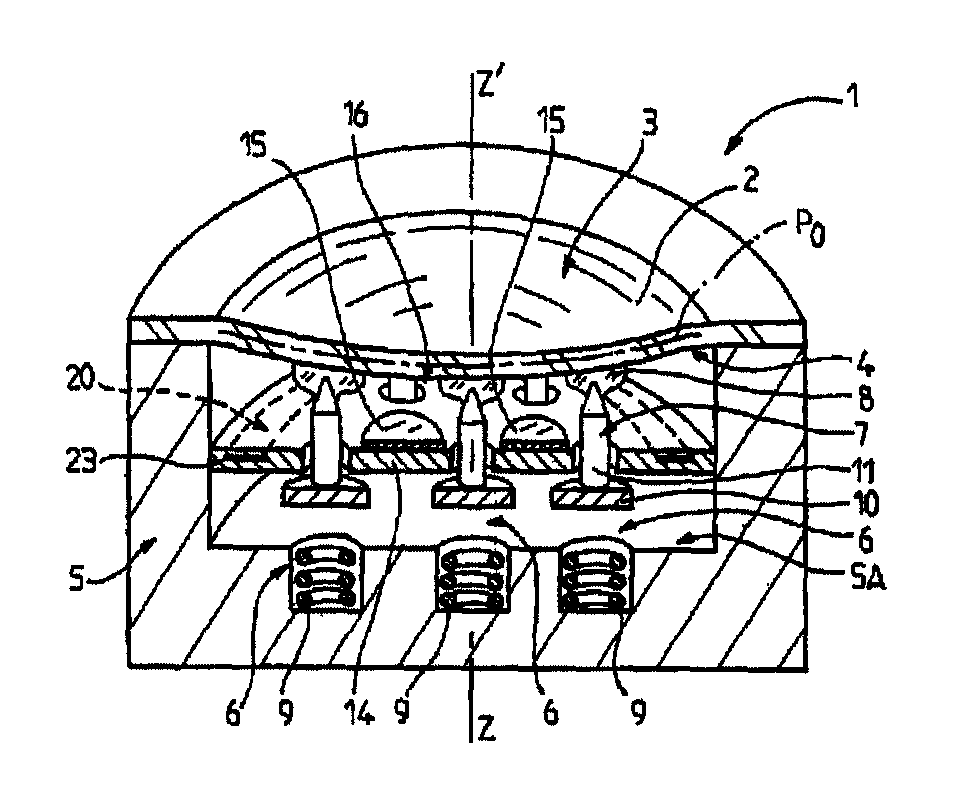
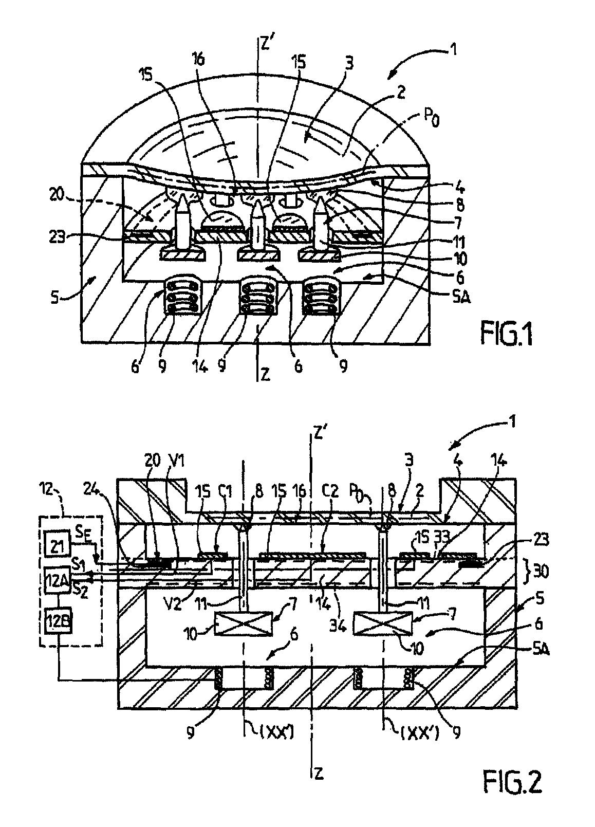
[0032]The present invention pertains to a system 1 comprising a mobile and / or deformable surface 2. By “mobile” is meant here the fact that said surface 2 is liable to move at least locally, and optionally globally (solid displacement). By “deformable” is meant here the fact that said surface 2 is liable to undergo a dimensional change or a change of shape under the effect of the application of a force. Of course, the surface 2 can move globally and deform simultaneously, in which case its displacement decomposes locally into a component of solid displacement and a component of displacement by deformation. Ultimately, the surface 2 is therefore a shifting surface.

[0033]For example, the system 1 may form a loudspeaker, in which case the surface 2 consists of the external face of a loudspeaker electro-acoustic membrane. According to another example, the system 1 can constitute a pressure sensor, in which case the surface 2 consists of the external fa...


PUM


Abstract

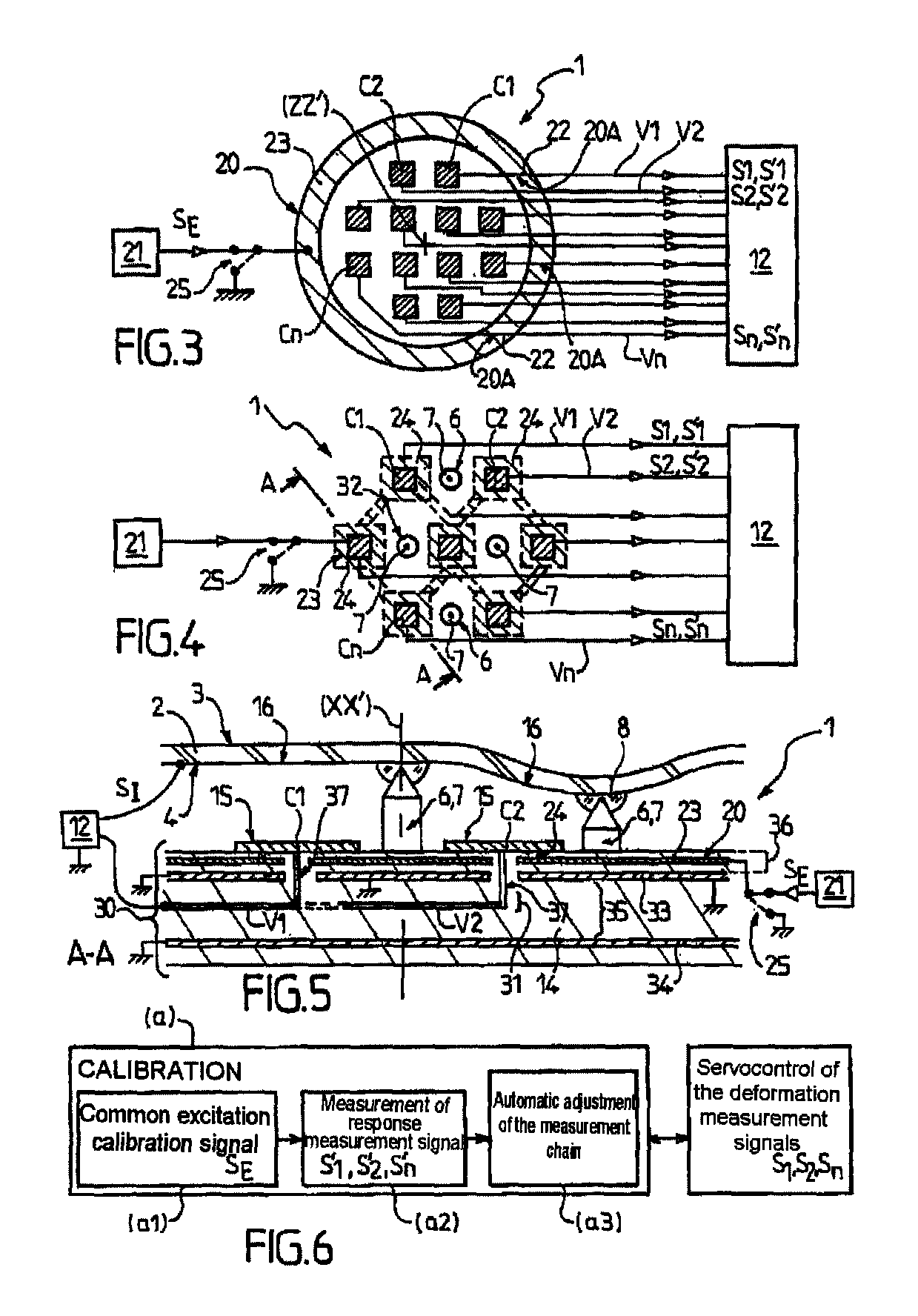
The invention relates to a system (1) comprising a deformable surface (2) and a first and a second sensor (C1, C2) designed to provide a first and a second measurement signal (S1, S2) intended to be collected by a processing circuit (12), said system (1) comprising first and second measurement paths (V1, V2) for collecting the first and second measurement signals (S1, S2), said system (1) being characterized in that it comprises a common calibration member (20) for simultaneously injecting into the first and second measurement paths (V1, V2) a calibration signal (SE), said common calibration member (20) being designed so that the image signals (S′1, S′2, S′n) restored via said measurement paths (V1, V2, Vn) are independent of said movable surface (2). Deformable movable surface systems, of the deformable mirror type.

Description

CROSS-REFERENCE TO RELATED APPLICATIONS[0001]This application is a §371 national stage of PCT International Application No. PCT / FR2012 / 053042, filed Dec. 21, 2012, claiming priority of French Patent Application No. 1162542, filed Dec. 29, 2011, the contents of each of which are hereby incorporated by reference in their entirety.TECHNICAL FIELD[0002]The present invention pertains to the general field of systems with mobile and / or deformable surface, such as for example pressure sensors, loudspeakers, or in a preferential manner, deformable mirrors used in adaptive optical systems, for applications as diverse as astronomy, medicine, in particular ophthalmology, telecommunications, metrology, etc.[0003]The present invention pertains more particularly to a system comprising a mobile and / or deformable surface as well as at least one first and one second sensor designed to provide respectively a first and a second measurement signal relating to the shape and / or to the position of said mob...

Claims


Application Information

Patent Timeline
IPC IPC(8): G01B11/14G02B26/08G01L27/00G01B11/24
CPCG01B11/14G01B11/24G02B26/0825G02B26/0816G01L27/002
Inventor BARRAULT, MICHEL RAYMOND
Owner ALPAO
Learn More