

Connector cover
a technology of connecting rods and connectors, applied in the direction of connecting rods, electrical equipment, coupling devices, etc., can solve the problems of easy damage, easy load application to the locking portion of the vertically divided cover is easily divided
- Summary
- Abstract
- Description
- Claims
- Application Information
AI Technical Summary
Benefits of technology
Problems solved by technology
Method used
Image

Examples
embodiment 1
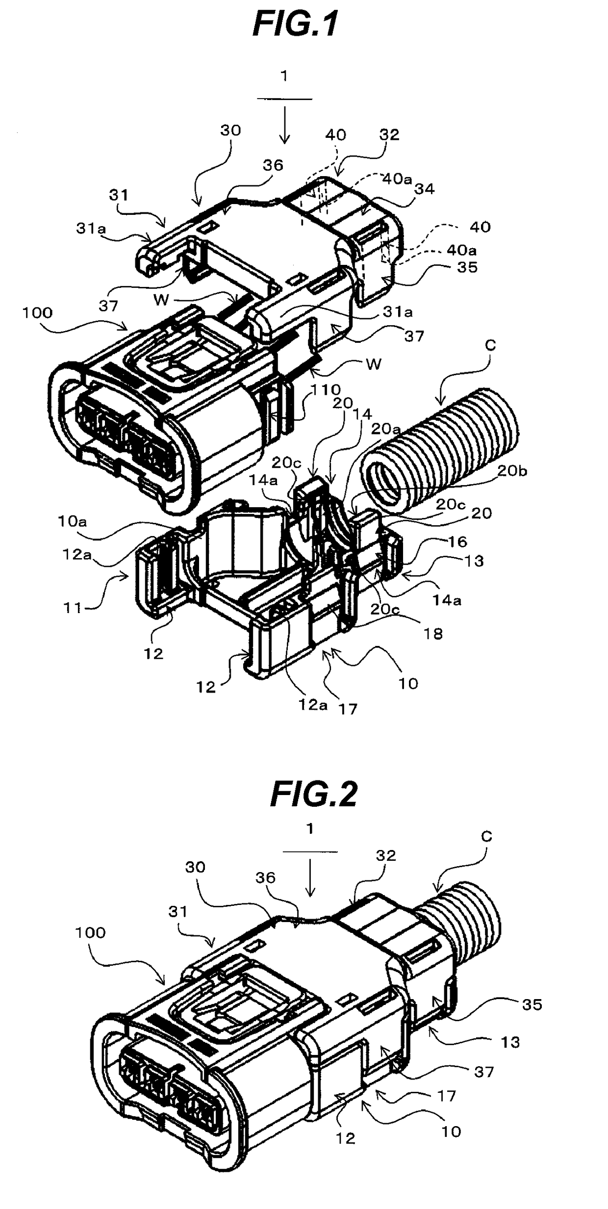
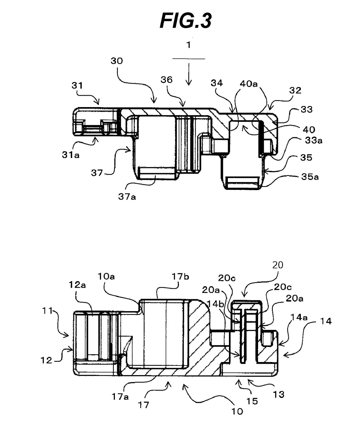
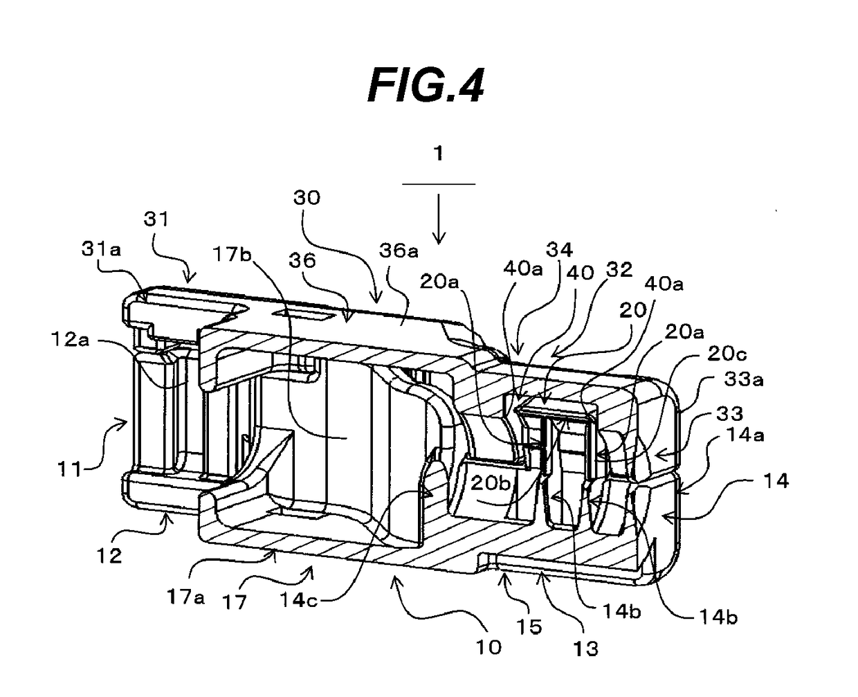
[0034]FIG. 1 is a view showing a state of a connector cover 1 according to an embodiment 1 before an upper cover 30 and a lower cover 10 thereof are assembled together so as to sandwich an end of a connector housing 100 and an end of a corrugated tube C. FIG. 2 shows a state of the connector cover 1 according to the embodiment 1 in which the upper cover 30 and lower cover 10 are assembled together so as to sandwich the end of the connector housing 100 and the end of the corrugated tube C. FIG. 3 is a section view of the upper side cover 30 and lower cover 10 in a state where they face each other in their mutually locking direction. FIG. 4 is a section view of the connector cover 1 in a state where upper cover 30 and lower cover 10 are locked to each other. FIGS. 5A to 5D are multiple views of the lower cover 10 when viewed from different directions: Specifically, FIG. 5A is a perspective view; FIG. 5B is a top view; FIG. 5C is a view when viewed from the side thereof to be connected...
embodiment 2
[0094]Next, description is given of a connector cover 2 according to an embodiment with reference to FIGS. 10, 11A and 11B.
[0095]FIG. 10 is a view showing a state before an upper cover 30 and a lower cover 10 of the connector cover 2 according to the embodiment 2 are assembled together so as to sandwich an end of a connector housing 100 and an end of a corrugated tube C. FIG. 11A is a perspective view of the upper cover 30, and FIG. 11B is a perspective view of the lower cover 10.
[0096]The connector cover 2 according to the embodiment 2 is different from the connector cover 1 of the embodiment 1 in that it includes ribs 50 which respectively extend continuously from the outer surfaces of the two side walls 14a, 14a of the tube placement wall 14 of the lower cover 10 to the outer surfaces of the pair of elastic hold arms 20, 20.
[0097]The remaining configurations are similar to the embodiment 1. The same composing parts as the embodiment 1 are given the same designations and thus the ...
embodiment 3
[0116]Next, description is given of a connector cover 3 according to an embodiment 3 with reference to FIGS. 13 to 15.
[0117]FIG. 13 is a view showing a state before an upper cover 30 and a lower cover 10 of the connector cover 3 according to the embodiment 3 are assembled together so as to sandwich an end of the connector housing 100 and an end of a corrugated tube C. FIG. 14A is a top view showing a state where the upper cover 30 and lower cover 10 of the connector cover 3 according to the embodiment 3 are assembled together so as to sandwich the end of the connector housing 100 and the end of the corrugated tube C. FIG. 14B is a section view of the lower cover 10 and the corrugated tube C set on the lower cover 10, taken along the B-B line shown in FIG. 14A. FIG. 15 is a perspective view of the upper cover 30.
[0118]The connector cover 3 according to the embodiment 3 is different from the connector cover 1 according to the embodiment 1 in the following points: that is, a pair of el...
PUM
 Abstract
Description
Claims
Application Information