Supercharge Your Innovation With Domain-Expert AI Agents!

Rifle scope with zero lock

a rifle scope and zero lock technology, applied in the field of rifle scopes, can solve the problems of excessive manufacturing costs, shooting loss of zero point by one or more rotations, and inability to see the indicia of the elevation turret,

Active Publication Date: 2019-05-02
LEUPOLD & STEVENS
View PDF0 Cites 7 Cited by
  • Summary
  • Abstract
  • Description
  • Claims
  • Application Information

AI Technical Summary

Benefits of technology

The present invention is an improved rifle scope with zero lock. It has all the advantages of prior art and solves the disadvantages. It includes a body with an internal movable optical adjustor, a knob, an indicator skirt, and a knob stop surface. The indicator skirt moves axially with the knob, and the knob and indicator skirt establish a limit of rotational travel. This invention solves the problem of prior art where the indicator skirt didn't move axially and could cause difficulty in adjusting the optical adjustor.

Problems solved by technology

However, this creates the potential for the shooter to lose track of the zero point by one or more rotations both when rotating towards the zero point and when rotating away from the zero point even when the elevation turret's indicia are visible.
Furthermore, the shooter may not be able to see the elevation turret's indicia when lighting conditions are poor.
However, these have various disadvantages including complexity and excessive manufacturing costs.
Some also require continuous squeezing to keep the rotatable adjustment knob unlocked, which make it more difficult to accomplish multiple fine rotation adjustments during an aiming operation.
Most prior art rifle scopes have no revolution indicator, but allow multiple turns of a rotatable turret, which makes it easy for a shooter to get “lost” and lose track of how many turns have been made.
Some scopes have a dial that moves up and down, and there is a fixed sleeve inside or outside of the dial that helps indicate the revolution the rifle scope is currently at, but in most cases the revolution indicator either cannot be reset or is susceptible to getting moved and losing its revolution setting when hit on the top of the dial.
In addition, since the movement of the dial on those scopes is directly proportionate to the pitch of the adjustment threads, the dial only moves a very small vertical amount each turn, making those marks very small and close together, which results in difficulty reading them.
This design has the disadvantage of not providing a precise, positive stop point.
Furthermore, the wedging resistance point is subject to change with repeated use as a result of wear.

Method used


Image

  • Rifle scope with zero lock
  • Rifle scope with zero lock
  • Rifle scope with zero lock

Examples


Embodiment Construction

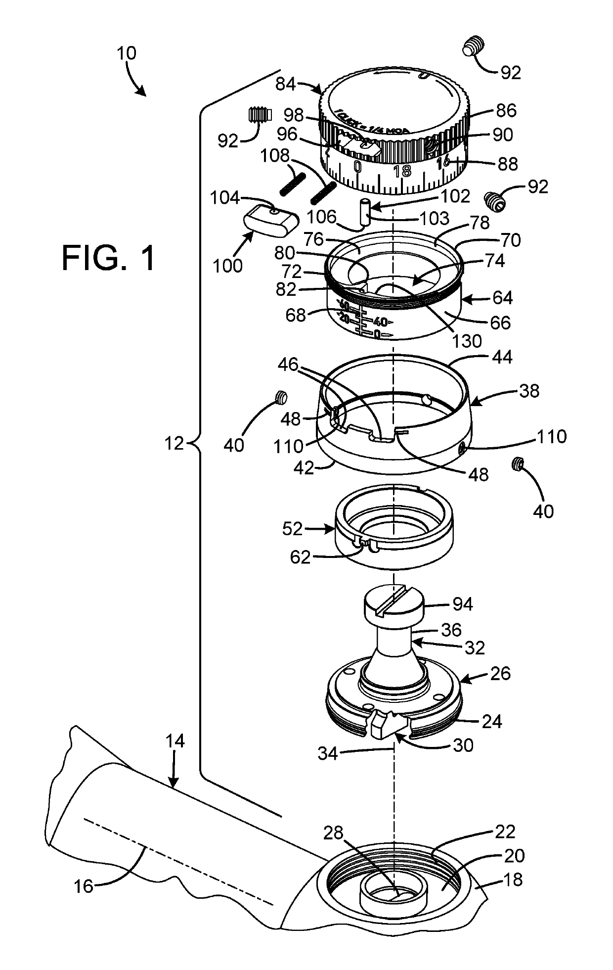
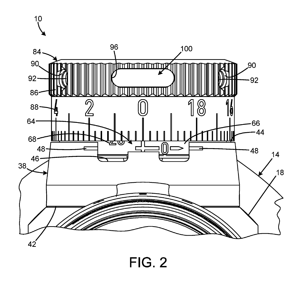
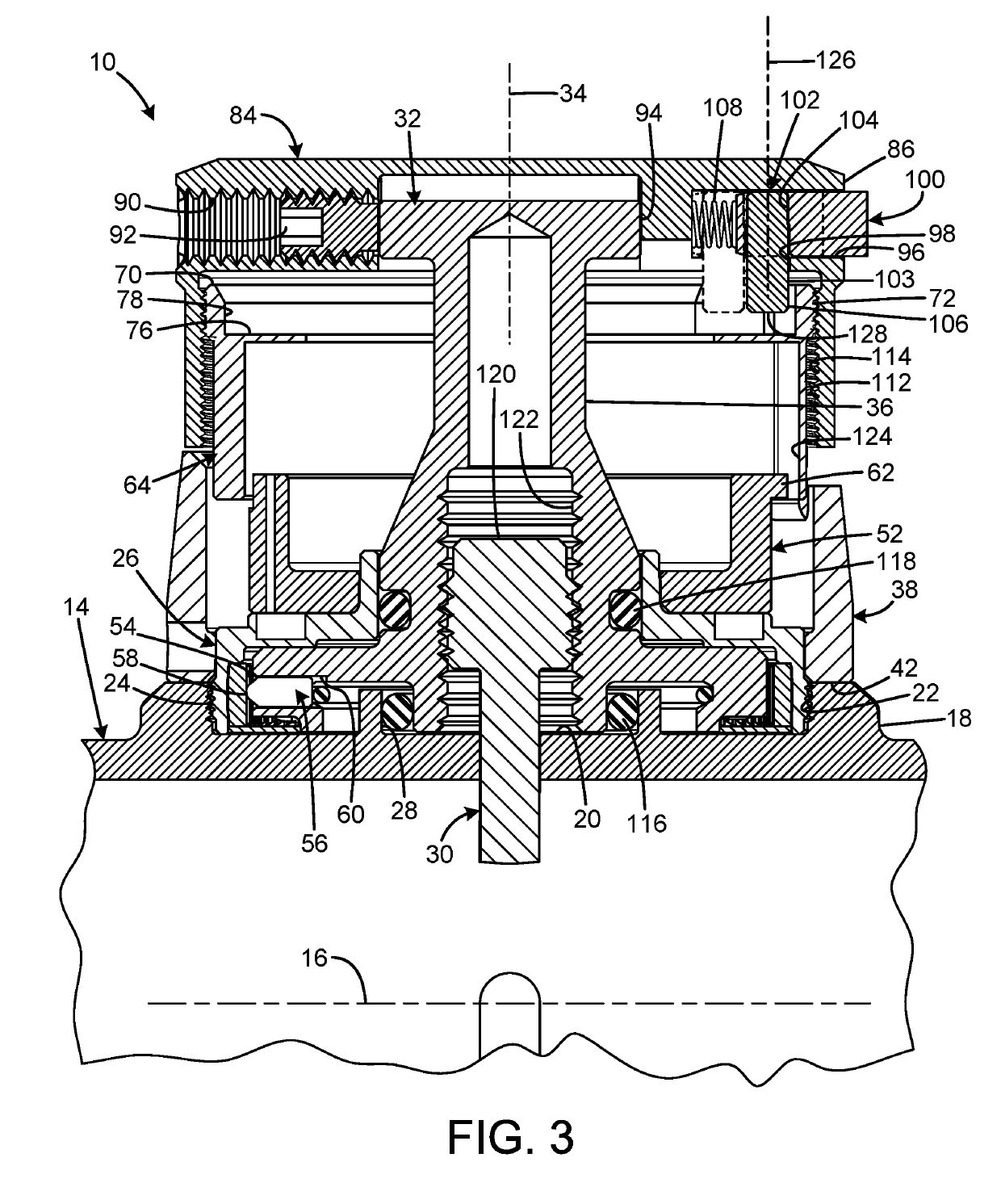
[0023]A current embodiment of the rifle scope with zero lock of the present invention is shown and generally designated by the reference numeral 10.

[0024]FIGS. 1-4 illustrate the improved rifle scope with zero lock 10 of the present invention. More particularly, the rifle scope with zero lock has an elevation turret 12 mounted to a main tube 14 of the rifle scope. Within the main tube, at least one adjustable element, such as a reticle, lens assembly, or other optical or electrical elements (not shown), may be movably mounted in a substantially perpendicular orientation relative to a longitudinal tube axis 16. The main tube further includes a seat 18, which has a bore 20 sized to receive the elevation turret. The bore includes threads 22 formed on an interior wall or shoulder that mate with corresponding exterior threads 24 on a turret flange 26 to releasably secure the elevation turret to the main tube when the elevation turret is installed.

[0025]The bore 20 defines slot 28 that is...


PUM


Abstract

Rifle scopes with zero locks or stops have a body having an internal movable optical adjustor adapted to shift an image generated by the riflescope, a knob connected to the body for rotation about a knob axis and operably connected to the optical adjustor to position the optical adjustor based on a rotational position of the knob, an indicator skirt rotatably engaged to the body and threadedly engaged to the knob, the indicator skirt being operable to move axially with respect to the knob such that the axial position of the indicator skirt is based on the rotational position of the knob, and the knob including a knob stop surface and the indicator skirt including a skirt stop surface, wherein the knob stop surface and the skirt stop surface are configured to positively contact each other to establish a limit of rotational travel of the knob.

Description

CROSS-REFERENCE TO RELATED APPLICATION[0001]This application claims the benefit of U.S. Provisional Patent Application No. 62 / 577,767 filed on Oct. 27, 2017, entitled “ZERO LOCK IMPROVEMENT,” which is hereby incorporated by reference in its entirety for all that is taught and disclosed therein.FIELD OF THE INVENTION[0002]The present invention relates to riflescopes, and more particularly to a rifle scope with a turret having a locking feature that releasably secures the turret in the zero point position or a stop feature that stops the dial at the zero position. The turret also includes a revolution indicator that displays the revolution currently in use.BACKGROUND OF THE INVENTION[0003]Sighting devices such as rifle scopes have long been used in conjunction with weapons and firearms, such as rifles, handguns, and crossbows, to allow a shooter to accurately aim at a selected target. Because bullet and arrow trajectory, wind conditions, and distance to the target can vary depending u...

Claims


Application Information

Patent Timeline
Patent Type & Authority Applications(United States)
IPC IPC(8): F41G1/38
CPCF41G1/38
Inventor DAVIS, MATTHEW C.JUENEMANN, TODD A.
Owner LEUPOLD & STEVENS
Features
  • R&D
  • Intellectual Property
  • Life Sciences
  • Materials
  • Tech Scout
  • Unparalleled Data Quality
  • Higher Quality Content
  • 60% Fewer Hallucinations
Learn More