

Image processing apparatus, image processing method, and image processing program
a technology of image processing and image processing method, applied in the field of image processing apparatus, a non-transitory recording medium, can solve the problem of relatively large arithmetic processing load required for generation, and achieve the effect of reducing the arithmetic processing load
- Summary
- Abstract
- Description
- Claims
- Application Information
AI Technical Summary
Benefits of technology
Problems solved by technology
Method used
Image


Examples
first embodiment
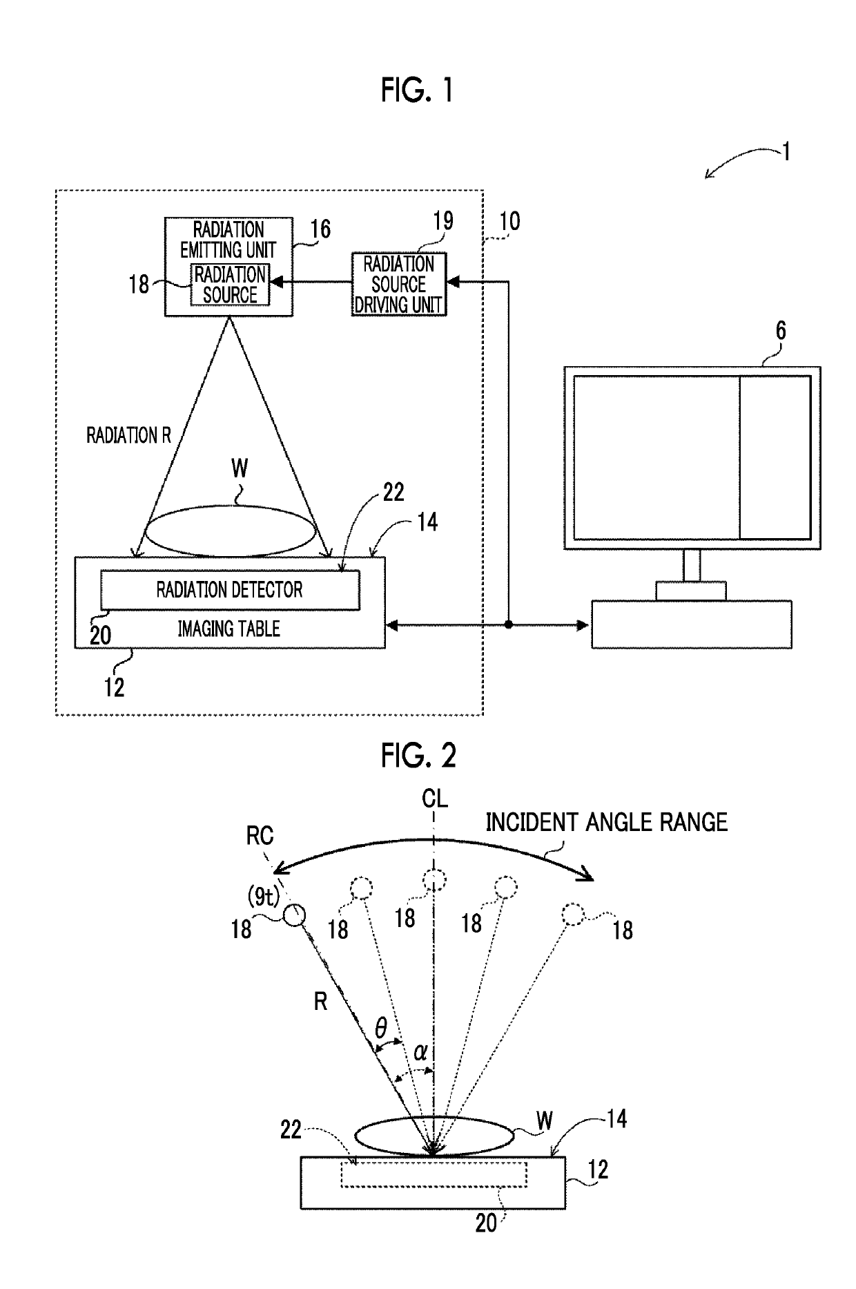
[0033]First, an example of the overall configuration of a radiography system according to this embodiment will be described. FIG. 1 is a diagram illustrating an example of the overall configuration of a radiography system 1 according to this embodiment. In addition, FIG. 2 is a diagram illustrating tomosynthesis imaging (which will be described in detail below) by a radiography apparatus 10 according to this embodiment.
[0034]As illustrated in FIG. 1, the radiography system 1 according to this embodiment comprises a console 6 and the radiography apparatus 10. In the radiography system 1 according to this embodiment, the radiography apparatus 10 captures a radiographic image of a subject W on the basis of a command (imaging order) input from an external system (for example, a radiology information system (RIS)) through the console 6 in response to the operation of a user such as a doctor or a radiology technician.
[0035]FIG. 3 is a block diagram illustrating an example of the configura...
example 1
[0058]First, a case in which a slab image is generated from three tomographic images, that is, a tomographic image 60z+d with a height of z+d, a tomographic image 60z with a height of z, and a tomographic image 60z−d with a height of z−d as illustrated in FIG. 5 will be described.
[0059]As illustrated in FIG. 5, a pixel 62z+d of the tomographic image 60z+d and a pixel 62z−d of the tomographic image 60z−d are located at the same position in the x direction and the y direction (the directions along the plane of the tomographic image 60z) as a pixel 62z of the tomographic image 60z and are different from the pixel 62z of the tomographic image 60z in height. In other words, the pixel 62z+d, the pixel 62z, and the pixel 62z−d have the same x-coordinate value and y-coordinate value. The pixel 62z+d corresponds to a pixel 72z+d at a position where a straight line connecting the radiation source 18 and the pixel 62z+d intersects the projection image 70t. Similarly, the pixel 62z−d correspond...
example 2
[0063]The generation of a slab image which is equivalent to a case in which a slab image is generated from the tomographic images arranged at a narrower interval than that in Example 1 will be described with reference to FIG. 6. As illustrated in FIG. 6, a tomographic image 61z+e with a height of 60z+e (060z and the tomographic image 60z+d and a pixel 63z+e which is located at the same x-coordinate position and y-coordinate position as the pixels 62z−d, 62z, and 62z+d in the tomographic image 61z+e corresponds to a pixel 73z+e at a position where a straight line connecting the radiation source 18 and the pixel 63z+e intersects the projection image 70t. Therefore, the pixel 73z+e is located between the pixel 72z and the pixel 72z+d. In addition, a tomographic image 61z−e with a height of 60z−e is present between the tomographic image 60z and the tomographic image 60z−d and a pixel 63z−e which is located at the same x-coordinate position and y-coordinate position as the pixels 62z−d, ...
PUM
 Abstract
Description
Claims
Application Information