Packing Tool and Process
- Summary
- Abstract
- Description
- Claims
- Application Information
AI Technical Summary
Benefits of technology
Problems solved by technology
Method used
Image

Examples
Example
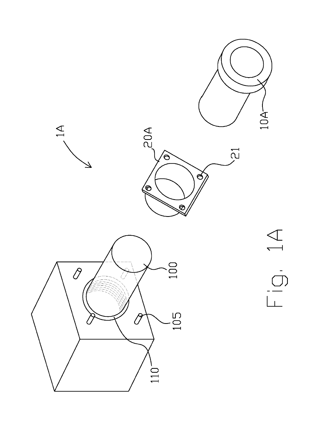
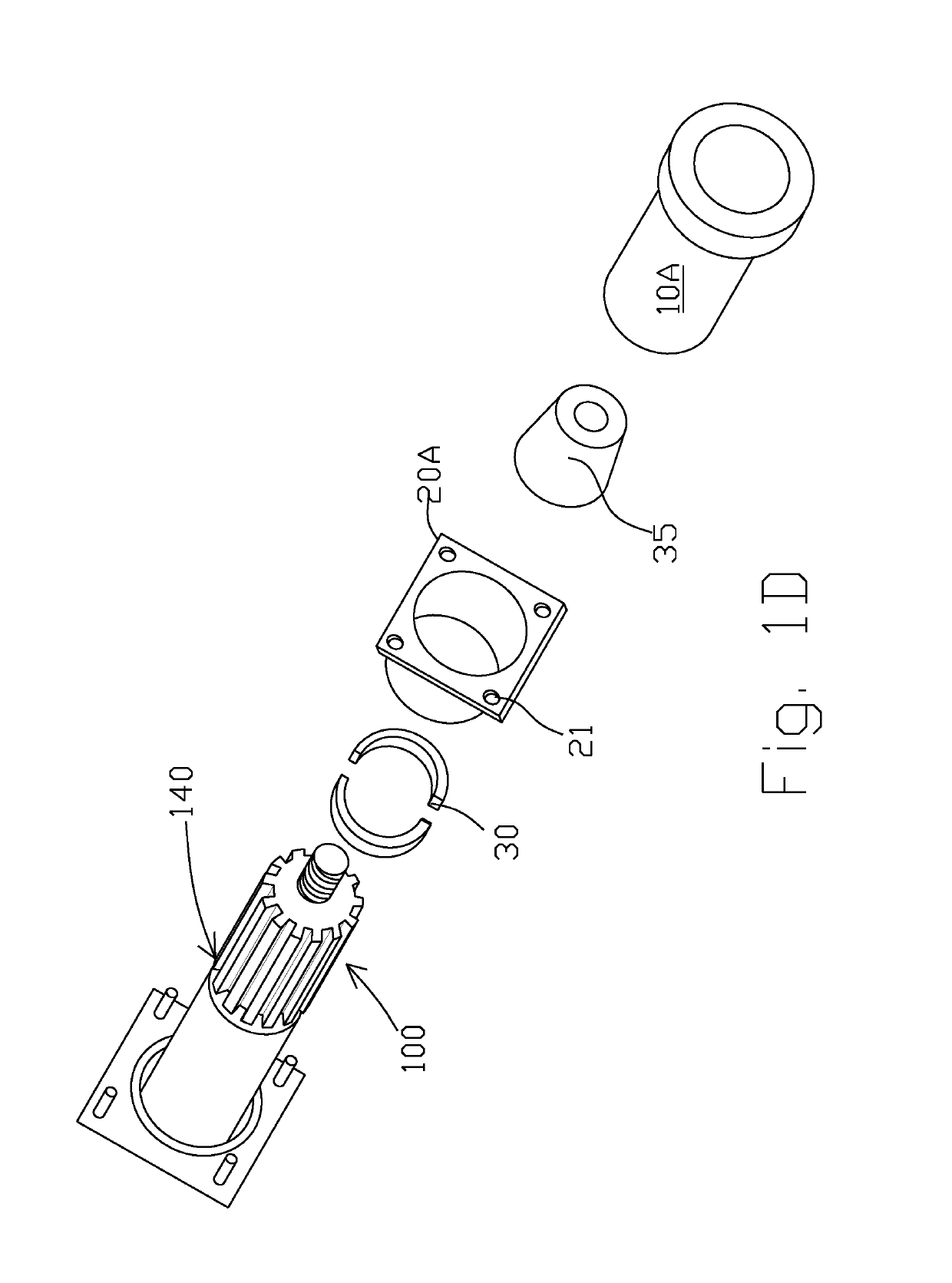
[0022]FIG. 1A is an exploded view of a first embodiment of the invention 1A for use in an instance where a free end of a shaft is easily accessible. This assembly 1A comprises a tapered gland 20A with a packing pusher 10A. Both of these are slipped over the free end of the shaft. The terms “proximal” and “distal” are orientated such that the invention is in front of the user with the proximal end being near the user and the distal end being closer to the gland that is being packed to create a seal. The pushing packer 10A includes a proximal end formed generally in the shape of a toroid and having a distal end formed in the shape of cylinder attached thereto. The distal end of the pushing packer 10A preferably includes a groove, represented in FIG. 1B as an inverted V. The groove contacts the V-packs to seat them about the shaft 100 when creating a seal. The proximal toroidal end of the pushing packer 10A is gripped by the user and used to push the V-packs into place to create a seal...
Example
[0026]FIG. 2A is an exploded view of the second embodiment of the invention showing a split tapered gland 20B and a hinged packing pusher 10B. As shown in FIGS. 2A-2B, the split tapered gland 20B and the hinged packing pusher 10B are configured about shaft 100, as shaft 100 does not have a free end. Thus, the split tapered gland 20B and hinged packing pusher 10B are configured about shaft 100 as shown in FIG. 2B. A distal end of the tapered gland 20B, is slid into the packing gland 110. Packing member 120 is sliced such that it may be configured about the shaft 100. Thereafter, packing member 120 is pushed through split tapered gland 20B and into the packing gland 110. Successive packing members 120 are stacked into the packing gland 110 to create a seal. As can be recognized when viewing FIG. 2A, hinged packing pusher 10B is cut into two pieces and having one of the cut edges coupled together with a hinge 11. Split tapered gland 20B comprises external undulations 24. Dowels 22 are ...
Example
[0027]FIG. 3A is a perspective exploded view of a third embodiment of the invention and showing an adjustable hinged packing pusher 10C, a master plate 25 and a split adapter plate 40. The master plate 25 and split adapter plate 40 serve essentially the same purpose as the tapered glands 20A, 20B of the first and second embodiments mentioned above. That is, the assembled master plate 25 and split adapter plate 40 guide the packing member 120 into a gland 110 to be packed. In this embodiment, the adjustable hinged packing pusher 10C comprises hinge 11 which allows it to be fitted over a shaft and locked together via a locking pin 16 which slips into a pair of offset mating holes 17. Pin 16 is shown as being inserted into one of the offset mating holes 17. Each side of the open end of the adjustable hinged packing pusher 10C includes an offset opening, one arranged at a higher elevation than the other such that they overlap one above the other when the adjustable hinged packing pusher...
PUM
| Property | Measurement | Unit |
|---|---|---|
| Diameter | aaaaa | aaaaa |
Abstract
Description
Claims
Application Information
 - R&D Engineer
- R&D Manager
- IP Professional
- Industry Leading Data Capabilities
- Powerful AI technology
- Patent DNA Extraction
Browse by: Latest US Patents, China's latest patents, Technical Efficacy Thesaurus, Application Domain, Technology Topic.
© 2024 PatSnap. All rights reserved.Legal|Privacy policy|Modern Slavery Act Transparency Statement|Sitemap