
Bicycle parking device

a technology for parking devices and bicycles, applied in the field of bicycle parking devices, can solve the problems of difficult lifting and moving a bicycle, inconvenient u-shaped stands, damage to bicycles, etc., and achieve the effects of simplifying and facilitating bicycle parking, and expanding the opportunities for its usability

Active Publication Date: 2019-10-31
UAB PARKIS
View PDF0 Cites 1 Cited by
  • Summary
  • Abstract
  • Description
  • Claims
  • Application Information

AI Technical Summary

Benefits of technology

This invention is a bicycle parking device that aims to simplify and lower the cost of parking bicycles. It was designed to be easily usable in different spaces, and can be positioned and used in different ways. The device uses a wheel fixing mechanism to securely and safely parking bicycles in different positions. It reduces parking time and ensures stability of the lifted bike. The device also includes a wheel support that can accommodate various types of wheels and tires. The pads protect the wheel rim from damage and scratches.

Problems solved by technology

These U-shaped stands are inconvenient because bicycles parked in this way occupy a large space that could be used for other purposes.
For bicycle parking where bicycles are hung on a hook on a wall, it is difficult to lift and move a bicycle, as it requires high physical strength, the bicycle may fall, and the bicycles can be damaged during lifting or lowering.
Thus this method of hanging is not very convenient.
A shortage of the known bicycle parking device is that the device is for parking several bicycles, therefore it takes up a lot of space, has a complex structure that requires a large amount of various structural elements and a motor which needs electric power sources or other power generation systems.
This causes the increase in the price of a device, moreover, it requires a special parking place which would be provided with power sources to lift the bicycle; thus, its use is limited.

Method used


Image

  • Bicycle parking device
  • Bicycle parking device
  • Bicycle parking device

Examples


Embodiment Construction

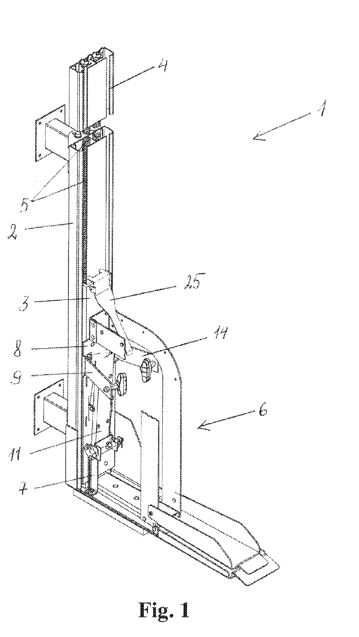
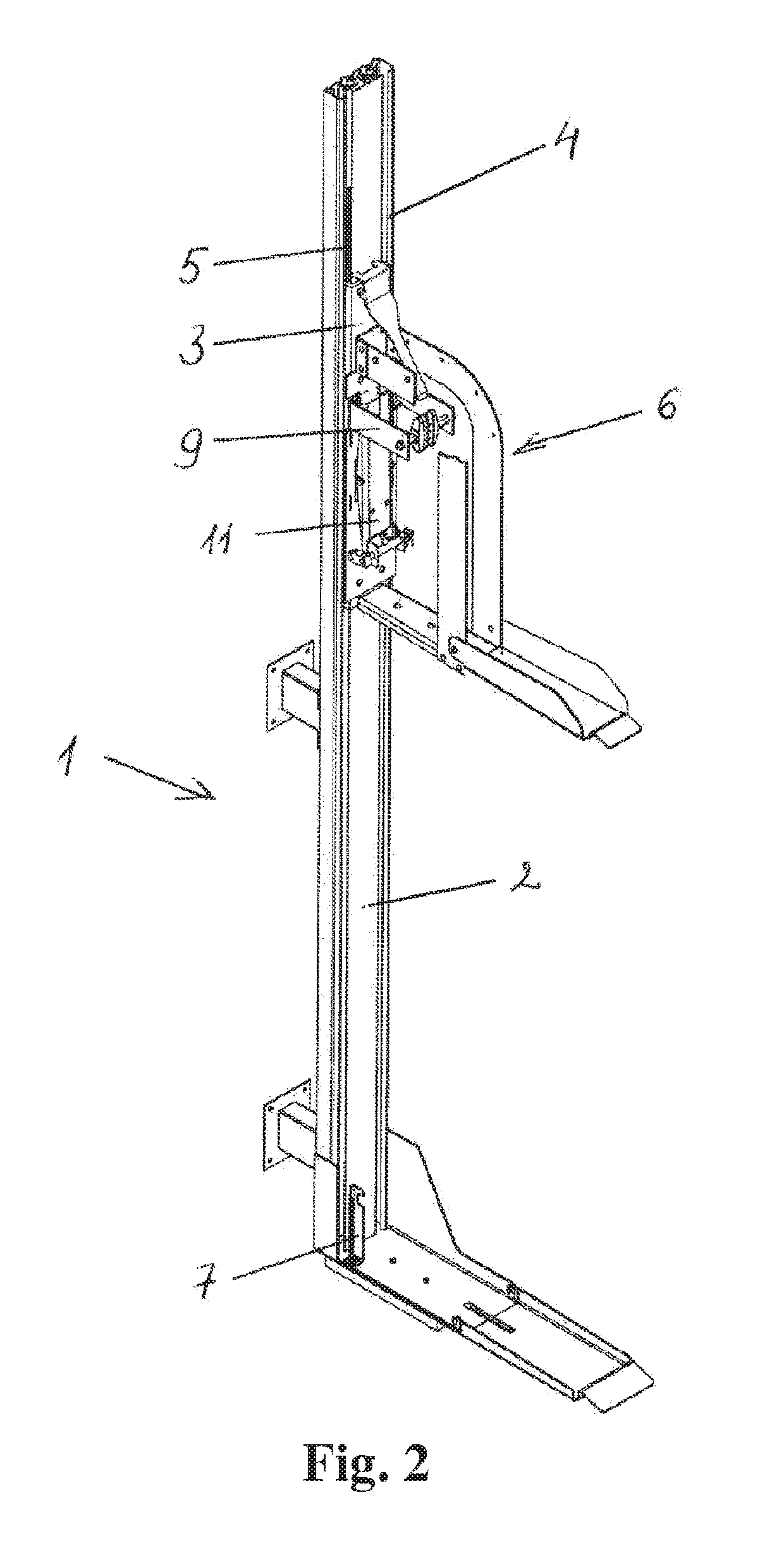
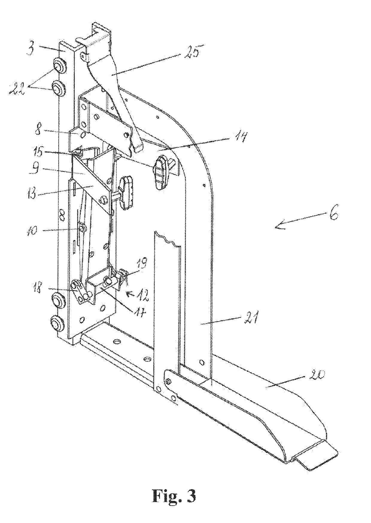
[0027]The bicycle parking device 1 comprises a stand 2, trolley 3 mounted in the stand with the possibility to move in it on guides 4 and connected to the lifting unit 5. The wheel fixing mechanism 6 is mounted on the mentioned trolley 3. The lifting unit 5 is an elastic element, for example, two springs 5 or a rubber connected with the upper end to the upper part of the stand 2, and the other end is fixed to the trolley 3 and the elastic element is tight when the trolley 3 is in lower position. Elasticity of the lifting unit 5 is selected such as to ensure rising of the wheel to rear parking position, which depending on the chosen elasticity of a spring or rubber may be any position from horizontal to vertical position. A trolley fixing unit 7 fixedly mounted in the stand 2 may be a hook 7. The wheel fixing mechanism 6 has the base 8 attached to the trolley 3 where a wheel holder 9 is attached to its upper part; the lever 11 is mounted on the horizontal axis 10 in the central part,...


PUM


Abstract

A bicycle parking device includes a stand and a trolley mounted in the stand and connected to a lifting unit, which has an elastic element connected with the stand and the trolley, where the elastic element is tight when the trolley is in a lower position. When a bicycle is positioned in an initial parking position, elasticity of the elastic element ensures the lift of the trolley to an upper position. When the bicycle is in the initial parking position with the wheel placed into a wheel fixing mechanism, it fixes the wheel and affects the trolley fixing unit to release and allow the elastic element to transfer the bicycle from the initial parking position to a rear parking position, and when the bicycle is transferred from the rear parking position to the initial position, the wheel fixing mechanism releases the wheel, transferring the trolley to a fixed position.

Description

FIELD OF THE INVENTION[0001]This invention relates to bicycle parking devices, especially to bicycle parking devices for fixing and holding a bicycle, in particular in a vertical position.DESCRIPTION OF THE RELATED ART[0002]A variety of bicycle parking devices and equipment, such as the widespread horizontal U-shaped bicycle parking stands or hooks on the walls for hanging bicycles, are known and used. These U-shaped stands are inconvenient because bicycles parked in this way occupy a large space that could be used for other purposes. For bicycle parking where bicycles are hung on a hook on a wall, it is difficult to lift and move a bicycle, as it requires high physical strength, the bicycle may fall, and the bicycles can be damaged during lifting or lowering. Thus this method of hanging is not very convenient.[0003]A bicycle parking device for parking several bicycles in a vertical position, forming a structure constructed from the column mounted on a platform, and which has a base...

Claims


Application Information

Patent Timeline
Patent Type & Authority Applications(United States)
IPC IPC(8): B62H3/12E04H6/00
CPCE04H6/005B62H3/12B62H2700/00
Inventor RAUBA, BRONIUSRADVILA, VYGANTAS
Owner UAB PARKIS
Learn More