

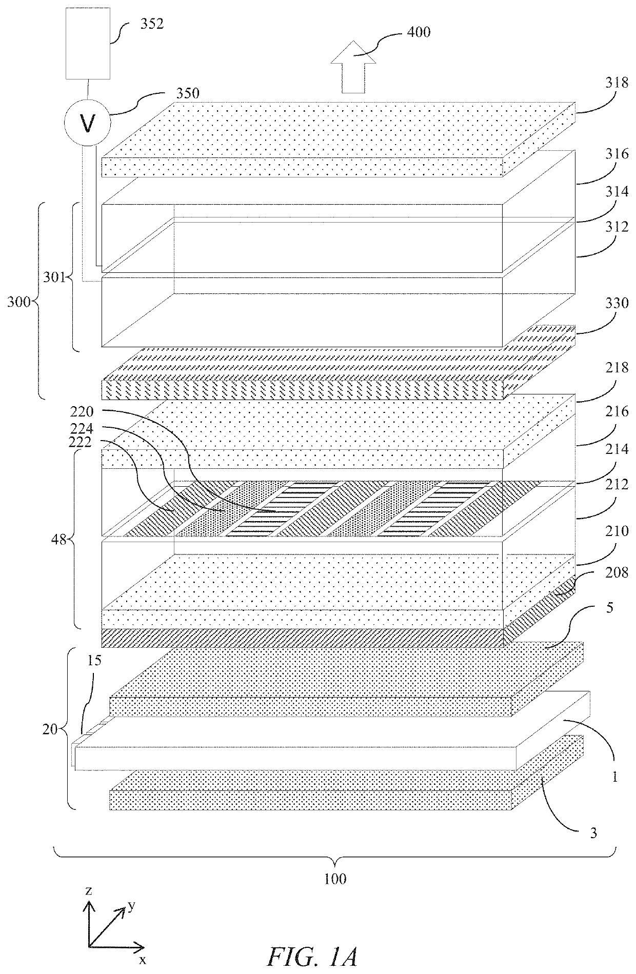
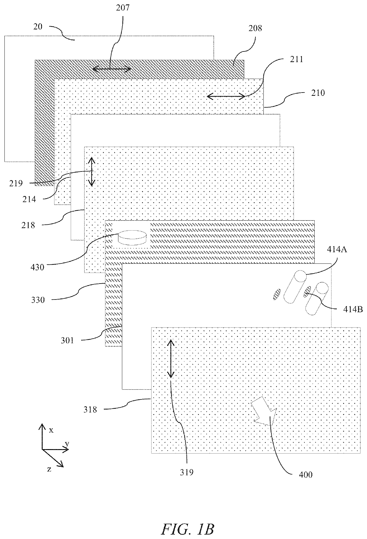
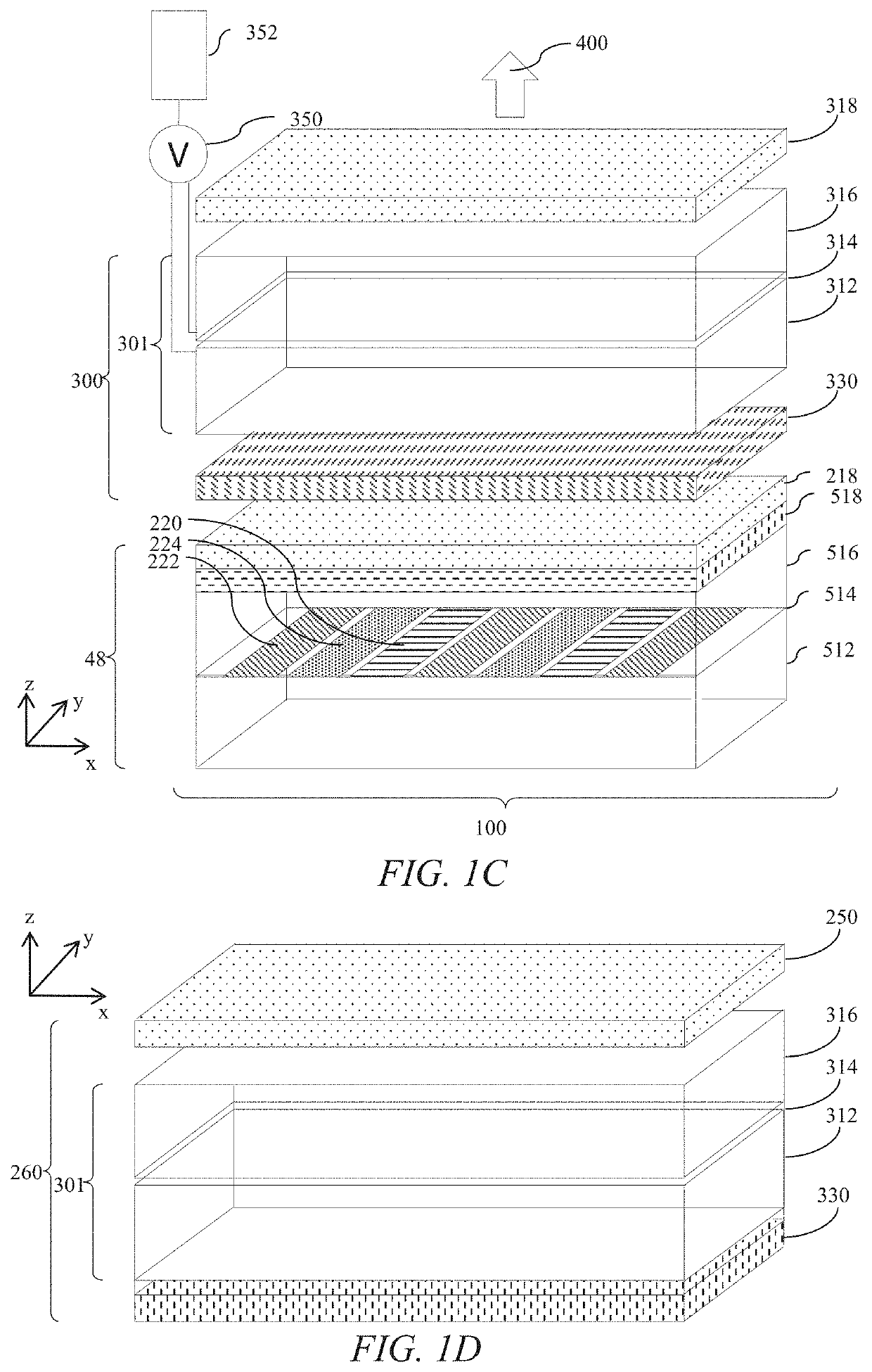
Optical stack for switchable directional display
a technology of optical stacks and directional displays, applied in non-linear optics, optics, instruments, etc., can solve the problems of increasing inventory and cost, high loss of film head-on illumination, moiré artefacts, etc., and achieve the effect of reducing the field of view of privacy displays, reducing cost and thickness, and reducing the cos
- Summary
- Abstract
- Description
- Claims
- Application Information
AI Technical Summary
Benefits of technology
Problems solved by technology
Method used
Image

Examples
Embodiment Construction
[0131]Terms related to optical retarders for the purposes of the present disclosure will now be described.
[0132]In a layer comprising a uniaxial birefringent material there is a direction governing the optical anisotropy whereas all directions perpendicular to it (or at a given angle to it) are optically equivalent.
[0133]Optical axis refers to the direction of propagation of an unpolarised light ray in the uniaxial birefringent material in which no birefringence is experienced by the ray. For light propagating in a direction orthogonal to the optical axis, the optical axis is the slow axis when linearly polarized light with an electric vector direction parallel to the slow axis travels at the slowest speed. The slow axis direction is the direction with the highest refractive index at the design wavelength. Similarly the fast axis direction is the direction with the lowest refractive index at the design wavelength.
[0134]For positive optical anisotropy uniaxial birefringent materials ...
PUM
| Property | Measurement | Unit |
|---|---|---|
| wavelength | aaaaa | aaaaa |
| wavelength | aaaaa | aaaaa |
| wavelength | aaaaa | aaaaa |
Abstract
Description
Claims
Application Information