Self-powered lighting for wheeled arrangements

a self-powered, wheeled technology, applied in the direction of cycle equipment, lighting and heating apparatus, lighting support devices, etc., can solve the problems of complex and expensive known constructions, and achieve the effect of improving the display of ligh

Inactive Publication Date: 2006-07-27
K & B INT
View PDF21 Cites 3 Cited by
  • Summary
  • Abstract
  • Description
  • Claims
  • Application Information

AI Technical Summary

Benefits of technology

[0011] In accordance with another feature of the invention, auxiliary light sources are mounted remotely from the wheel, and the generator is also coupled to these auxiliary sources to cause them to also emit light flashes during wheel rotation. An electrical conductor extends past the wheel to make electrical contact with the auxiliary sources. The auxiliary sources are stationary and are arranged in patterns to create an enhanced light display.

Problems solved by technology

The known constructions, however, are complex and expensive, especially when light flashing is desired for increased visual interest.

Method used


Image

  • Self-powered lighting for wheeled arrangements
  • Self-powered lighting for wheeled arrangements
  • Self-powered lighting for wheeled arrangements

Examples


Embodiment Construction

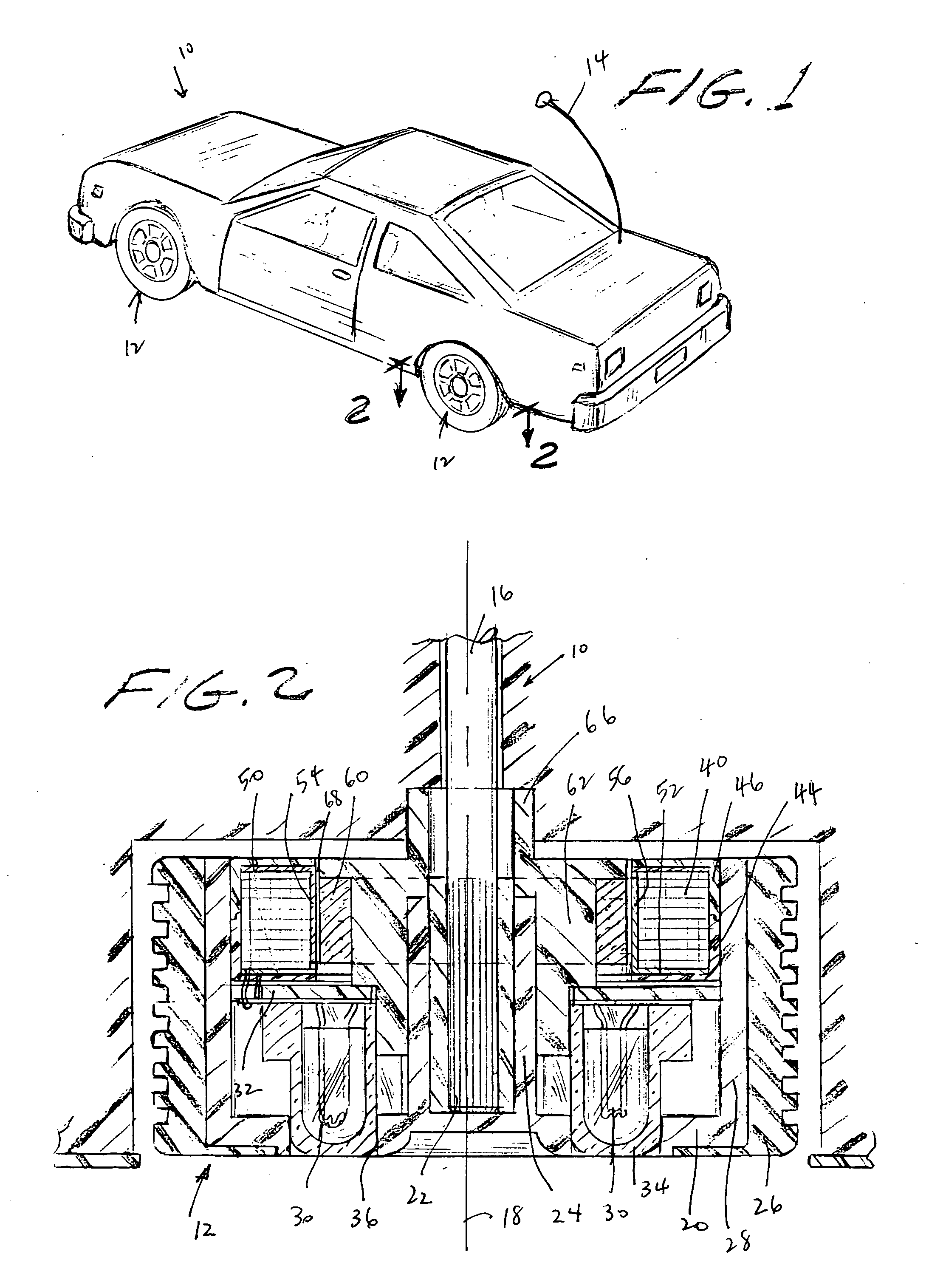
[0018]FIG. 1 depicts a radio-controlled toy vehicle 10 having a plurality of wheels 12 mounted for rotation thereon, and an antenna 14 for receiving radio frequency signals from a remote control unit (not illustrated) operative for communicating with an on-board drive motor (not illustrated) energizable for controlling movement of the vehicle.

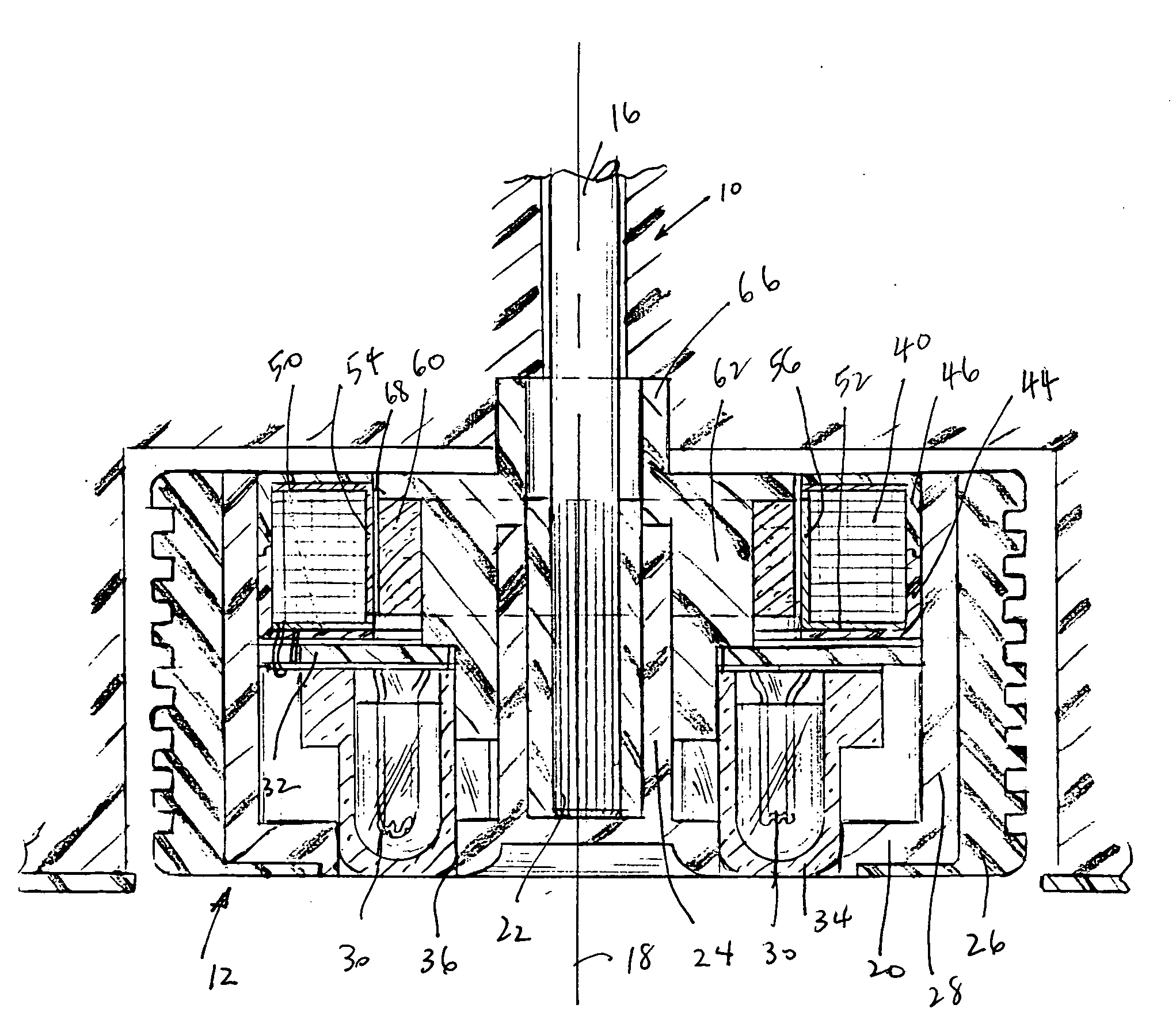
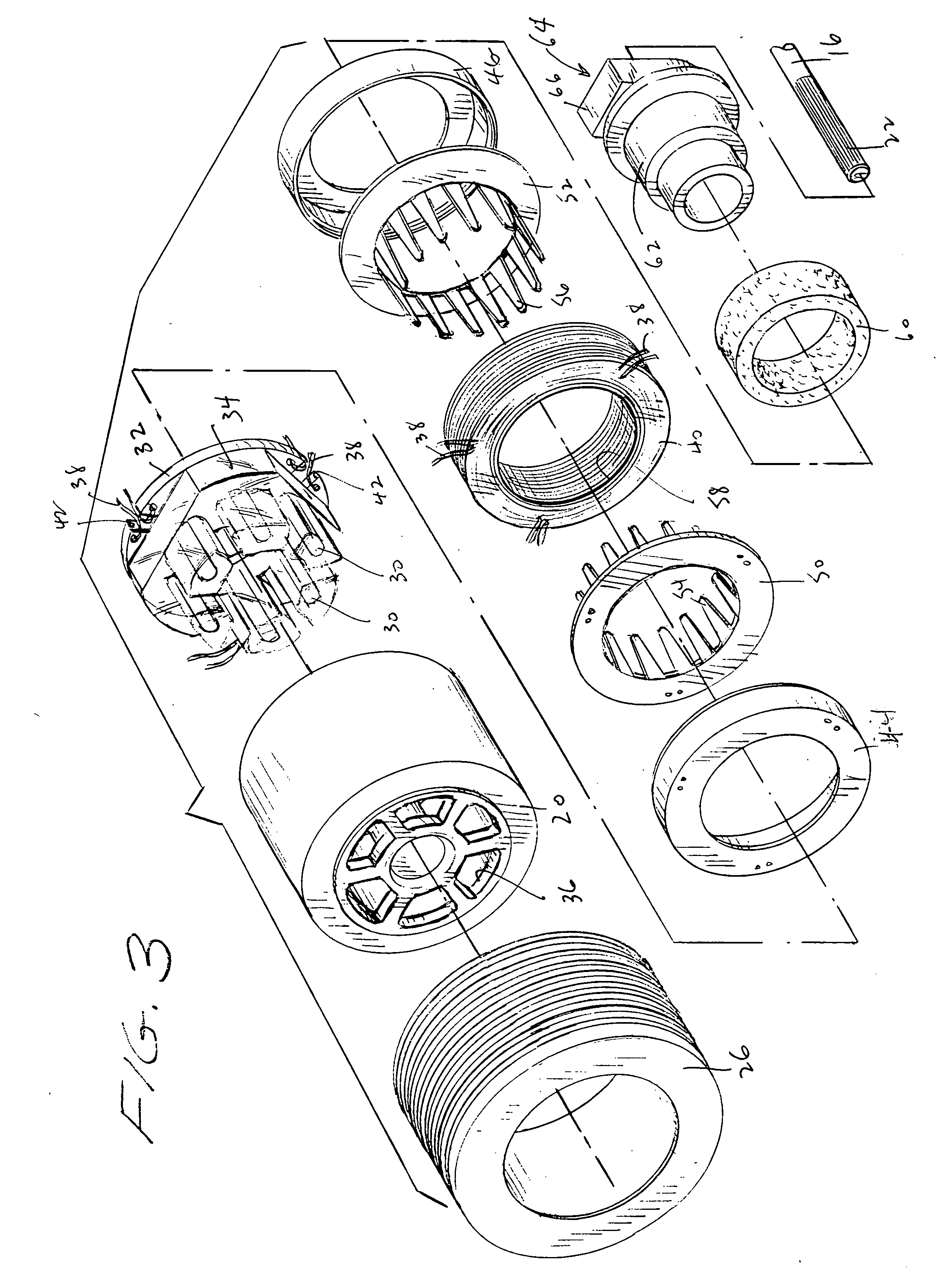
[0019] As best seen in FIG. 2, a rear drive axle 16 is mounted on the vehicle for rotation about an axis 18. Axle 16 has a splined end 22 fixedly received in a cylindrical bore 24 of a rotary housing 20. A traction tire 26 is frictionally fitted about a cylindrical outer part 28 of the housing. When the drive axle 16 is driven by the not illustrated drive motor, the housing and the tire are jointly rotated.

[0020] Also mounted in the housing 20 for joint rotation therewith is a plurality of light sources 30, preferably light emitting diodes (LEDs), mounted on an outer surface of a printed circuit board 32. A light-transmissive cover 34 enclose...


PUM


Abstract

A rotating wheel causes lights on and off the wheel to flash to create a light display. Moving pole teeth between a permanent magnet and an electromagnetic coil induce in the coil electrical pulses for flashing the lights.

Description

BACKGROUND OF THE INVENTION [0001] 1. Field of the Invention [0002] The present invention generally relates to electrical lighting that is powered by circuitry supported by wheels and, more particularly, to self-generating the power for displaying the lighting during rotation of the wheels. [0003] 2. Description of the Related Art [0004] It is generally known from Chinese Patent No. CN 2625000Y and CN 2624998Y to provide lights on wheels, and from U.S. Pat. No. 5,552,972 to provide a wheel capable of self-powered illumination during wheel rotation. In preferred applications, the lighted wheels are on novelty items such as toy cars or in-line skates. The known constructions, however, are complex and expensive, especially when light flashing is desired for increased visual interest. SUMMARY OF THE INVENTION Objects of the Invention [0005] Accordingly, it is a general object of this invention to advance the state of the art of providing wheels capable of self-illumination during rotati...

Claims


Application Information

Patent Timeline
Patent Type & Authority Applications(United States)
IPC IPC(8): H02K11/00H02K7/18F21V21/08
CPCA63C17/22A63C2203/14A63H17/262A63H17/28B60Q1/326B62J6/20
Inventor CHENG, CHEN WEITONG, CHEN WEIPEI, CHEN WEI
Owner K & B INT
Why Eureka
Try Eureka