Mounting system and associated kit for installing decorative lights

a technology for mounting systems and decorative lights, applied in decorative arts, lighting and heating apparatus, lighting support devices, etc., can solve problems such as unsightly marks on window glass, damage to the area surrounding the window, and not generally suitable for doing, and achieve the effect of maximum aesthetic appeal

Active Publication Date: 2016-06-02
RODAN ENTERPRISES LLC
View PDF6 Cites 6 Cited by
  • Summary
  • Abstract
  • Description
  • Claims
  • Application Information

AI Technical Summary

Benefits of technology

[0006]Accordingly, it is a general purpose and object of the present invention to provide an improved mounting system for installing decorative lights in and around windows of different sizes and configurations in a customized manner with maximum aesthetic appeal.

Problems solved by technology

Window frames are especially desirable for displaying holiday lights but not generally suitable for doing so.
Traditional methods of displaying holiday lights in a window have involved the use of tape, tacks, nails, suction cups, or other fasteners to hold the light strings in place within the window frame which often damage the area surrounding the window or leave unsightly marks on the window glass.
Makeshift mounting systems have been used for years and although the lights are quite attractive when installed, the installation of one string of holiday lights in a window is usually a painstaking activity, with the process of completing light installation on a group of windows, as is often the case, inevitably taking a significant amount of time.
While these and other prior art lighting mounting systems give all indications to work satisfactorily in providing a decorative light display for window frames, they have not been widely accepted and used by the general public due to certain limitations in the ability to fabricate, manufacture and assemble their support framework as well as difficulties in their mounting installations.
As a result, they have not been economically affordable and generally been available for implementation and use by the general public.
Furthermore, these prior art window frame lighting systems have also been limited to the extent that a user can easily adjust the set positioning of the lights in the resulting display to suit the desire and preference of the user and better complement the size and shape of the window to optimize the decorative effect.

Method used


Image

  • Mounting system and associated kit for installing decorative lights
  • Mounting system and associated kit for installing decorative lights
  • Mounting system and associated kit for installing decorative lights

Examples


Embodiment Construction

[0025]The following serves to describe a preferred embodiment of the present invention and the best presently contemplated mode of its production and practice. This description is further made for the purpose of illustrating the general principles of the invention but should not be taken in a limiting sense, the scope of the invention being best determined by reference to any associated claims.

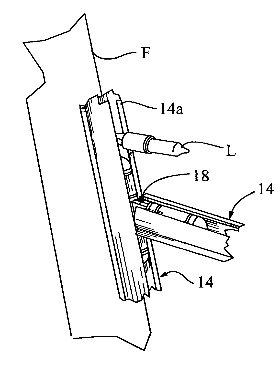
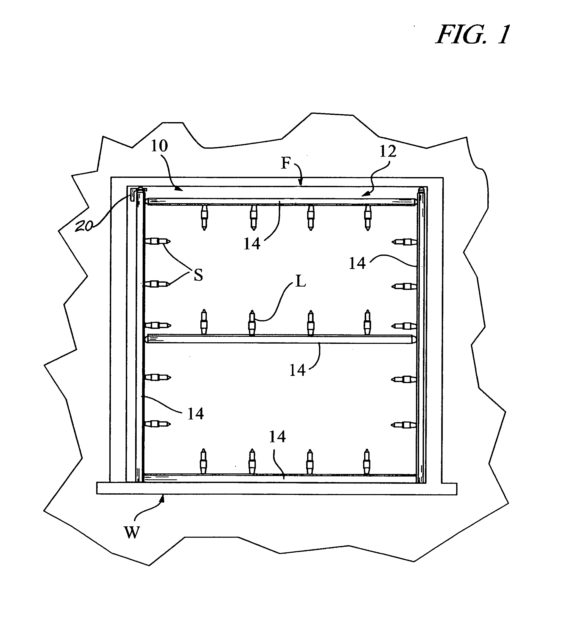
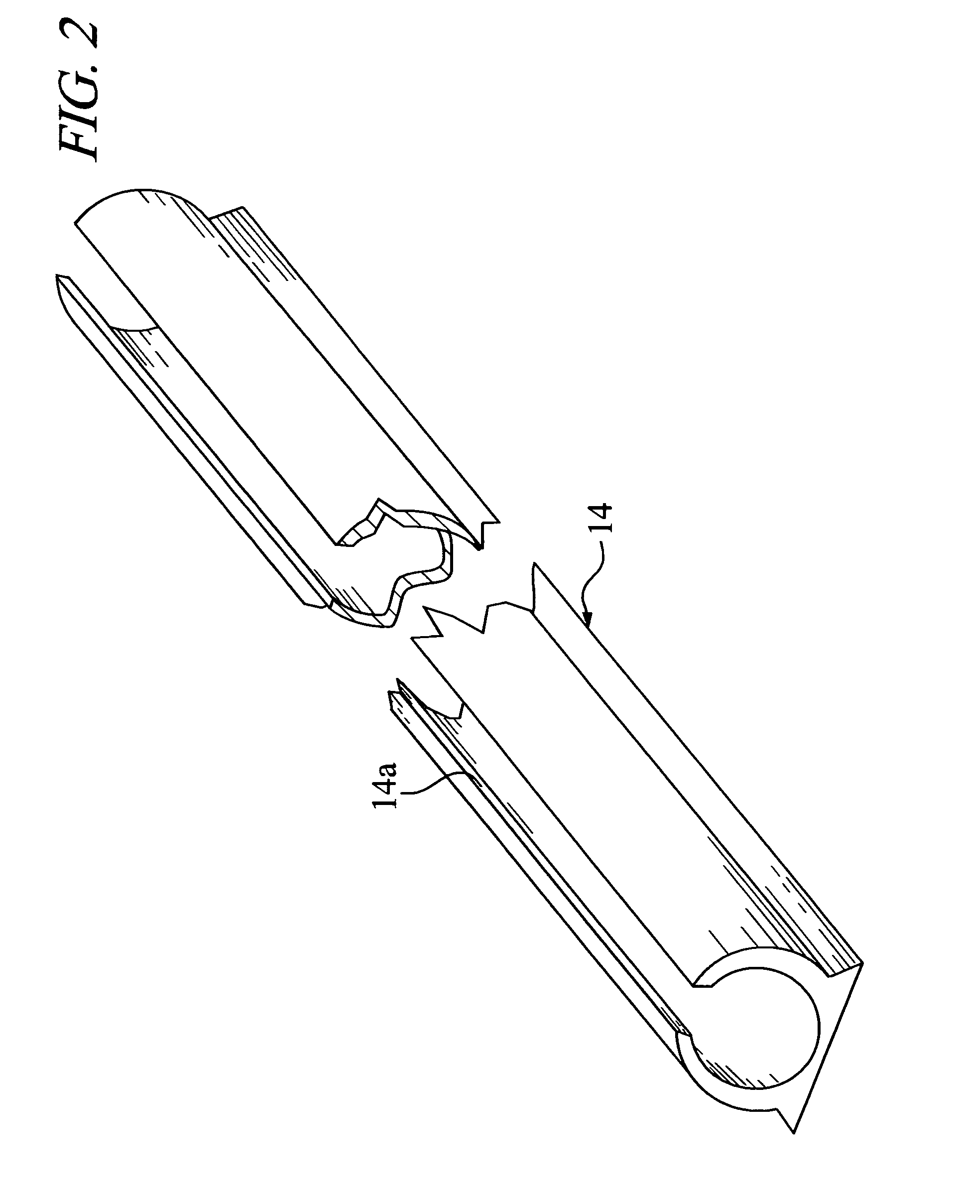
[0026]Referring to the drawings, the following is a list of structural componens of the present decorative light mounting system, generally designated 10, and those associated structural elements shown employed in connection with the present invention:[0027]10 decorative light mounting system;[0028]12 support framework assembly;[0029]14 tubular track member;[0030]14a slot opening;[0031]16 L-shaped connector;[0032]16a upright section;[0033]16b base section;[0034]16c rotational connection;[0035]17 O-ring members;[0036]18 T-shaped connector;[0037]18a transverse section;[0038]18b stem section;[003...


PUM


Abstract

An improved mounting system and associated kit is disclosed for installing decorative lights within a window frame. The present system comprises a support framework assembly of separate tubular track members, each having a slotted opening running along its length and together joined in a substantially rectangular configuration or in an alternative form intended to conform to the shape of the window frame. Separate L-shaped and T-shaped connectors constructed having movable projecting sections are sized and fitted with O-ring members to provide a press-fit engagement with the tubular chambers of the track members at their respective ends and thereby join the tubular track members together in their assembly and secure the assembly in mounted position within the window with the respective slotted openings inwardly facing. A light insertion tool specially formed and used in association with the present system allows the user to complete installation of a string of decorative lights within the slotted openings of the tubular track members with the individual lights set apart equidistantly for optimal aesthetic effect.

Description

CROSS-REFERENCE TO RELATED APPLICATION[0001]This application is a continuation-in-part of U.S. provisional patent application Ser. No. 62 / 123,889 filed Dec. 1, 2014 for Mounting System and Associated Kit for Installing Decorative Lights.BACKGROUND OF THE INVENTION[0002]The present invention relates to window-mounted systems for hanging decorative lighting and, more particularly, to an improved mounting system and associated kit for installing decorative lights within a window frame including a support framework assembly of slotted tubular members specially formed and interconnected so as to be adjustable for mounting in a variety of window frames together with an associated light insertion tool capable of readily installing the individual lights of a decorative light string equally spaced apart within the slotted tubular members.[0003]Throughout the United States and elsewhere, the practice of displaying decorative lighting on homes, apartments and other dwelling units at holiday ti...

Claims


Application Information

Patent Timeline
Patent Type & Authority Applications(United States)
IPC IPC(8): F21V21/34F21S4/10F21V17/14F21V21/088F21V17/10
CPCF21V21/34F21V21/088F21S4/10F21V17/14F21V17/107F21S4/28F21V21/02F21W2121/00
Inventor RUSSIKOFF, DANARUSSIKOFF, RONALD K.
Owner RODAN ENTERPRISES LLC
Why Eureka
Try Eureka