Decorative lighting system with improved support framework assembly

Active Publication Date: 2022-11-10
TWINKLETRAK LLC
View PDF5 Cites 0 Cited by
  • Summary
  • Abstract
  • Description
  • Claims
  • Application Information

AI Technical Summary

Benefits of technology

The present invention is an improved decorative lighting system for windows that can be customized to the shape and size of the window frame. It has a better constructed and easier to assemble and mount supporting framework, and can be flexibly adjusted to different window shapes and lights' positions to optimize the decorative effect. The lighting system is inexpensive and reliable over extended periods of usage. The supporting framework assembly includes a plurality of tubular track members and articulating end clips that engage with the track members to adjust to the shape of the window frame, and special light mounting clips that hold the lights in selected positions along the track members. The system can fold and store more easily for easy mounting and dismounting. Overall, the invention provides a more customized, flexible, and economical decorative lighting system for windows.

Problems solved by technology

Window frames are especially desirable for displaying holiday lights but not generally suitable for doing so.
Traditional methods of displaying holiday lights in a window have involved the use of tape, tacks, nails, suction cups, or other fasteners to hold the light strings in place within the window frame which often damage the area surrounding the window or leave unsightly marks on the window glass.
Makeshift mounting systems have been used for years and although the lights are quite attractive when installed, the installation of one string of holiday lights in a window is usually a painstaking activity, with the process of completing light installation on a group of windows, as is often the case, inevitably taking a significant amount of time.
While this prior art patented system does provide an effective installation of decorative lighting within a standard window frame, some limitations have been found with the rigid form of the resulting framework and its mounting and with maintaining desired placement of the lights in the slotted openings.
While these and other prior art lighting mounting systems give all indications to work satisfactorily in providing a decorative light display for window frames, they have not been widely accepted and used by the general public due to certain limitations in the ability to fabricate, manufacture and assemble their support framework as well as difficulties in their mounting installations.
As a result, they have not been generally affordable and easy to use by the general public.
Furthermore, these prior art window frame lighting systems have also been limited to the extent that a user can adjust the set positioning of the lights in the resulting display to suit the desire and preference of the user and better complement the size and shape of the window to optimize the decorative effect.

Method used


Image

  • Decorative lighting system with improved support framework assembly
  • Decorative lighting system with improved support framework assembly
  • Decorative lighting system with improved support framework assembly

Examples


Embodiment Construction

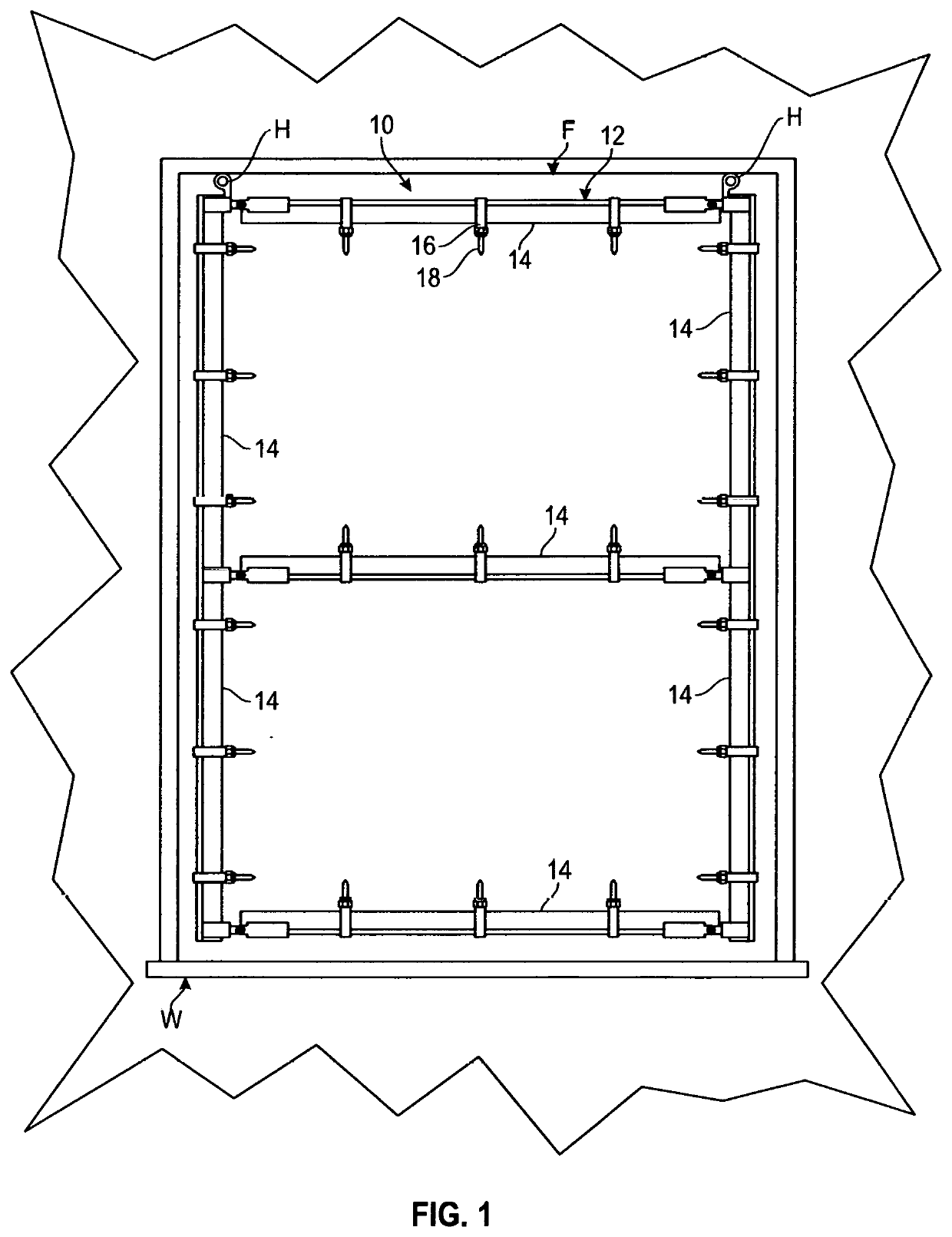
[0025]The following serves to describe a preferred embodiment of the present invention and the best presently contemplated mode of its production and practice. This description is further made for the purpose of illustrating the general principles of the invention but should not be taken in a limiting sense, the scope of the invention being best determined by reference to any associated claims.

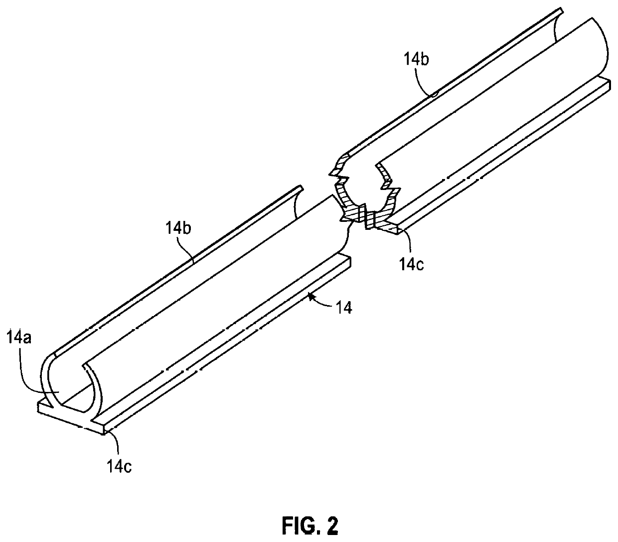
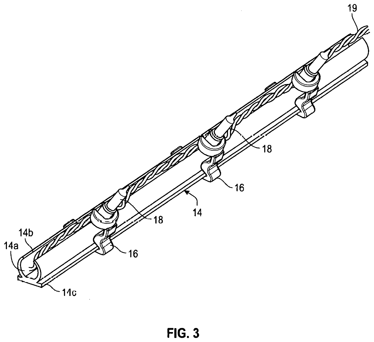
[0026]Referring to the drawings, the following is a list of structural components of the present decorative lighting system, generally designated 10, and those associated structural elements shown employed in connection with the present invention:[0027]10 decorative lighting system;[0028]12 support framework assembly;[0029]14 tubular track member;[0030]14a track member chamber;[0031]14b slotted opening;[0032]14c squared bottom edge;[0033]16 light mounting clip (preferred);[0034]16a light mounting clip head;[0035]16b light mounting clip base;[0036]16c light mounting clip neck;[0037]16d light mo...


PUM


Abstract

An improved decorative lighting system constructed having a support framework assembly for mounting decorative lights in connection with a window frame. The support framework assembly comprises a plurality of tubular track members, each formed having a slotted chamber section extending the length of the track member with a squared outer edge formed along either side at the base of the chamber to provide a substantially flat planar surface along the base of the track member. A plurality of articulating end clips are formed to engage each track member and interconnect with another to join the track members in a substantially rectangular configuration adjustable to conform to the shape of the window frame. A plurality of specially configured light mounting clips are formed to press-fit and slide along the flat perimeter surface of the track members and hold the decorative lights in selected positions along the track members. Ring members included upon selected ones of the articulating end clips are used and positioned in upper corners of the framework assembly to engage conventional hooks or tabs secured to the window frame and facilitate the mounting of the framework assembly and its removal and storage when desired. The articulating end clips further allow the complete support framework assembly to fold and store more easily.

Description

CROSS-REFERENCE TO RELATED APPLICATION[0001]This application claims the benefit of U.S. Provisional Application Ser. No. 63 / 258,513 filed May 7, 2021 for a Decorative Lighting System with Improved Support Framework Assembly.BACKGROUND OF THE INVENTION[0002]The present invention relates to window-mounted systems for installing decorative lighting and, more particularly, to a decorative lighting system for windows that includes an improved support framework assembly for mounting the system within a window frame with greater ease and further affording easy removal and storage when desired.[0003]Throughout the United States and elsewhere, the practice of displaying decorative lighting on homes, apartments and other dwelling units at holiday times has become increasingly wide spread. Traditionally, this practice of displaying holiday lights was most often implemented during the Christmas season, but recently, has become a more frequent and almost year-round exercise in enhancing other ho...

Claims


Application Information

Patent Timeline
IPC IPC(8): F21S4/28F21V21/005F21V21/04F21V21/30F21V21/088F21V33/00
CPCF21S4/28F21V21/005F21V21/047F21V21/30F21V21/088F21V33/006F21V23/002F21W2131/405F21S4/10
Inventor RUSSIKOFF, RONALD K.RUOOILROFF, DANA
Owner TWINKLETRAK LLC
Why Eureka
Try Eureka