LED light source with integrated circuit and light guide

a technology of led light source and integrated circuit, applied in the field of elongated light source, can solve the problems of low cost, and achieve the effect of improving light source performance, simple circuitry and reducing cos

Inactive Publication Date: 2008-02-21
OSRAM SYLVANIA INC
View PDF3 Cites 4 Cited by
  • Summary
  • Abstract
  • Description
  • Claims
  • Application Information

AI Technical Summary

Benefits of technology

[0005]Yet another object of the invention is the enhancement of light sources generally and elongated light sources in particular.
[0006]These objects are accomplished, in one aspect of the invention, by the provision of a light engine comprising: a thermally conductive substrate having a dielectric on one side thereof; upper and lower lens guards positioned near one end of the substrate; at least one LED mounted on the dielectric between the lens guards; and electrical conductors mounted upon the dielectric at another end thereof for supplying power to the LED. An elongated light source according to another aspect of the invention comprises: a subassembly including a base, a light engine positioned in mounting means formed in the base; a light guide positioned in spaced apart supports for receiving and distributing light from the LED, and a cover fixed to the base. This elongated light source provides an even, well distributed illumination and avoids the pinpoint of light display of the prior art. Also, it uses fewer LEDs and as a consequence, employs simpler circuitry, this combination resulting in a lower cost.

Problems solved by technology

Also, it uses fewer LEDs and as a consequence, employs simpler circuitry, this combination resulting in a lower cost.

Method used


Image

  • LED light source with integrated circuit and light guide
  • LED light source with integrated circuit and light guide
  • LED light source with integrated circuit and light guide

Examples


Embodiment Construction

[0013]For a better understanding of the present invention, together with other and further objects, advantages and capabilities thereof, reference is made to the following disclosure and appended claims taken in conjunction with the above-described drawings.

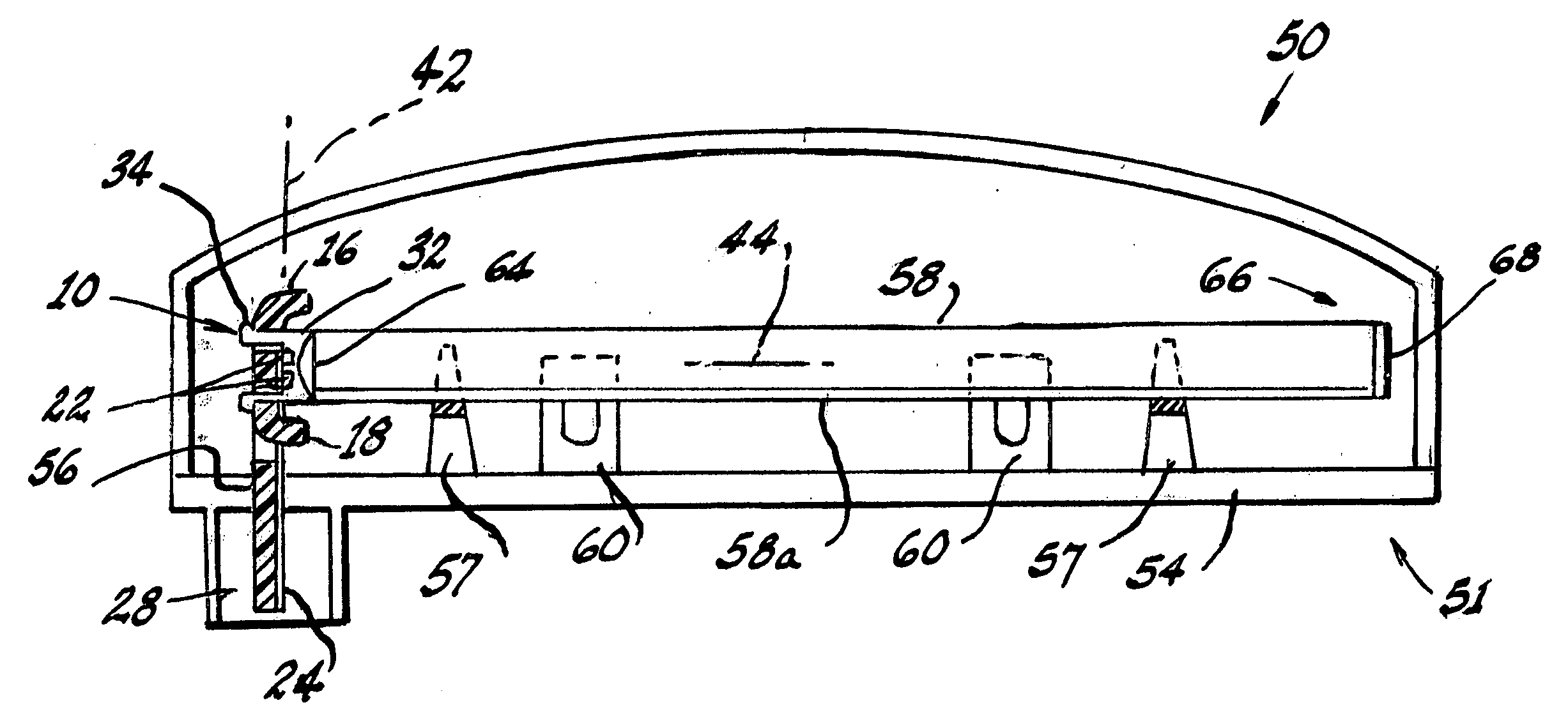
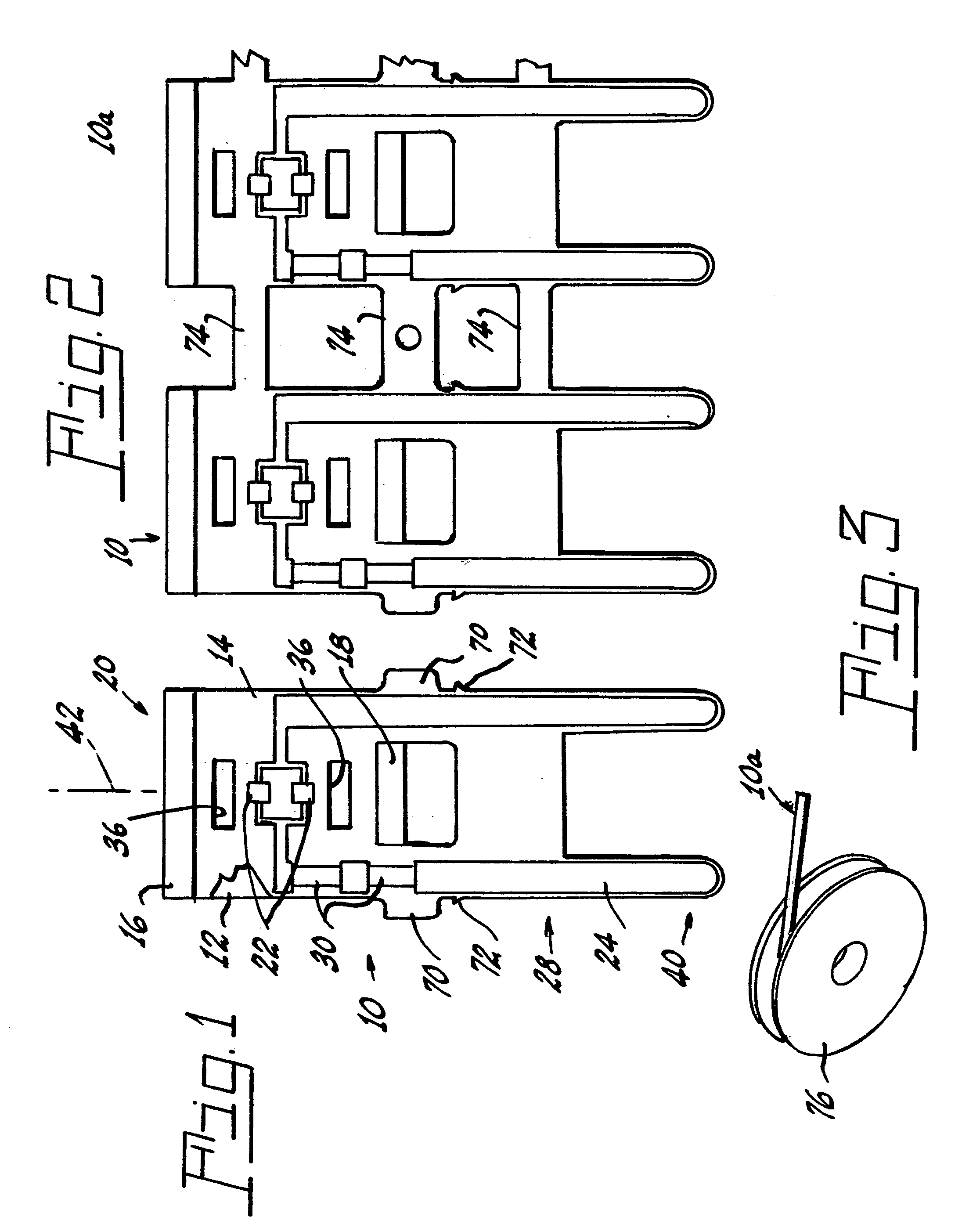
[0014]Referring now to the drawings with greater particularity, there is shown in FIG. 1 a light engine 10 comprising: a thermally conductive substrate 12 fabricated of a suitable material, such as aluminum, having a thermally conductive dielectric 14, such as ceramic-filled silicone, on one side thereof. Employing the thermally conductive material for the substrate 12 allows the substrate to function both as the supporting element and a heat sink. The use of a heat sink is important because, even though the heat generated by operation of the LEDs is less than that that would be supplied by incandescent bulbs, it can be sufficient to damage the LEDs when they are driven at high power.

[0015]Upper and lower lens guards, 16, 18, res...


PUM


Abstract

An elongated light source (50) comprises a subassembly (51) including a base (54), a light engine (10) positioned in mounting means (56) formed with the base; a light guide (58) positioned in spaced apart supports (57), and a cover (62) fixed to the base (54). The light engine (10) comprises a thermally conductive substrate (12) having a dielectric (14) on one side thereof; upper and lower lens guards, (16, 18), respectively, positioned near one end (20) of the substrate (12); at least one LED (22) mounted on the substrate between the lens guards (16, 18); and electrical conductors (24, 26) mounted upon the substrate at another end (28) thereof for supplying power to the LED (22).

Description

TECHNICAL FIELD[0001]This invention relates to light sources and more particularly to elongated light sources. Still more particularly it relates to light sources employing light emitting diodes (LED or LEDs) for elongated light sources that can be used as the center high mount stop light (CHMSL) for automotive vehicles.BACKGROUND ART[0002]The now ubiquitous CHMSL has utilized many varieties of light sources including incandescent, neon and LEDs. Because of their relatively long life and cool operating temperatures (when compared to incandescent light sources) LEDs have taken over the majority of these applications. However, their cost and complexity of manufacture have caused some concern in the industries using them. For example, most of the LED sources available for CHMSL use require a large printed circuit board and a large number of LEDs, each one usually associated with an individual lens. It is not uncommon for many brands of automobile to use six or more LEDs in this manner ...

Claims


Application Information

Patent Timeline
Patent Type & Authority Applications(United States)
IPC IPC(8): H01L33/00
CPCB60Q1/302H01L25/0753G02B6/0055F21K9/00H01L2924/0002H01L2924/00
Inventor SWANTNER, MICHAEL J.SEYMOUR, DOUGLAS G.
Owner OSRAM SYLVANIA INC
Why Eureka
Try Eureka