
Thin aspect lighting system with cutoff

a technology of forward lighting and thin aspect, applied in the field of thin aspect forward lighting system with cutoff, can solve the problems of difficult control, difficult modeling of beam photometry, and general excessive thickness of beams

Active Publication Date: 2020-11-12
VALEO NORTH AMERICA
View PDF0 Cites 0 Cited by
  • Summary
  • Abstract
  • Description
  • Claims
  • Application Information

AI Technical Summary

Benefits of technology

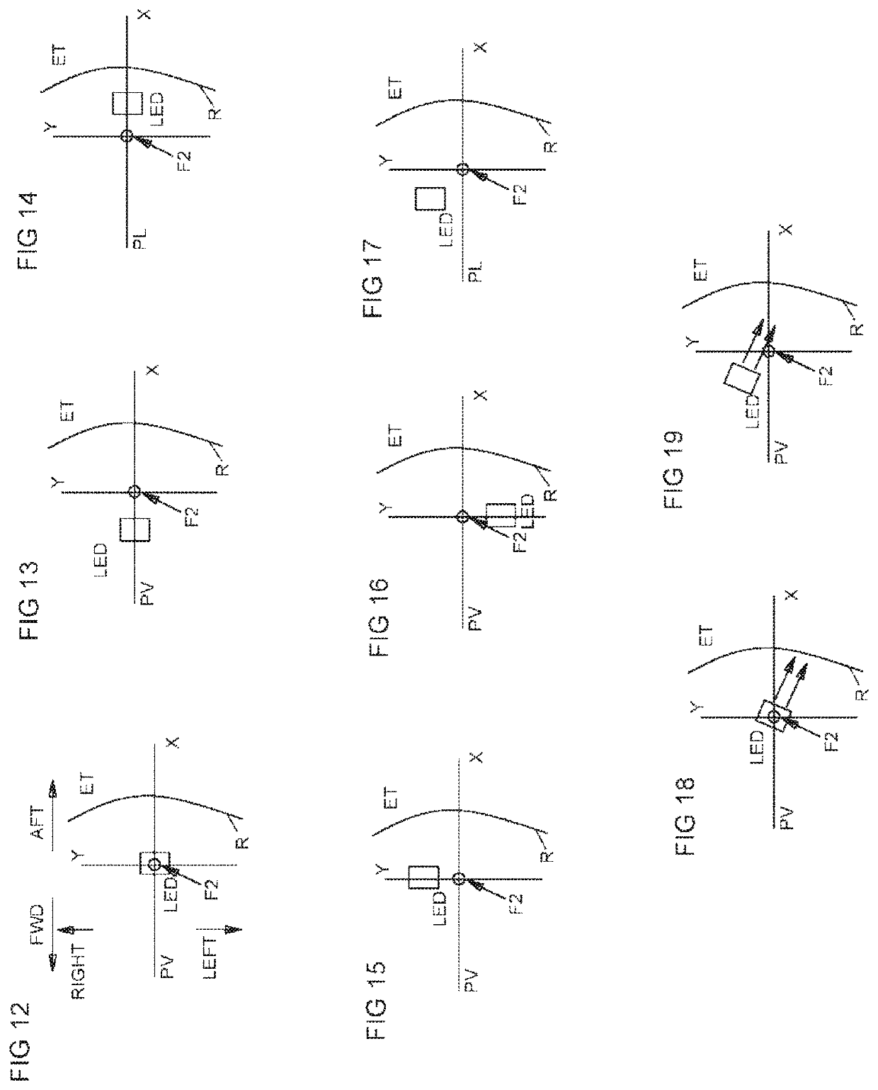
The patent describes a lighting device that uses a reflector to create a beam of light. The reflector has a specific shape that causes the light to be directed in a certain direction. In this patent, the light source is intentionally made to be off-center, or defocused, so that the light is directed to create a specific shape or kink in the beam. This allows for better control over the beam and can be useful in creating specific lighting effects.

Problems solved by technology

However, in this case, because of the large size of the images of the source generated by the mirror, the beam has in general an excessive thickness, and is in any case difficult to control.
On the other hand, the photometry of the beam may prove to be difficult to model, since by nature no correcting element of the prism or striated type can in general correct the light downstream of the lens; furthermore, these headlights have a large size depthwise.
The following are some additional problems with prior art designs:Conventional lens systems cannot be adapted to customer styling for thin lens elements.Conventional lens systems (imaging / projection lens systems) have color dispersion that may be objectionable when driving or must be managed in the design using more complex lenses.Conventional lens systems require more complex molding.

Method used


Image

  • Thin aspect lighting system with cutoff
  • Thin aspect lighting system with cutoff
  • Thin aspect lighting system with cutoff

Examples


Embodiment Construction

[0140]The invention improves over various prior art devices, including those shown in U.S. Pat. No. 7,980,742, to Albou, issued Jul. 19, 2011; U.S. Pat. No. 7,121,705 to Albou, issued October, 2006; U.S. Pat. No. 7,390,112, to Leleve, issued June, 2008; and U.S. Pat. No. 7,524,095, to Albou, issued April 2009, all of which are incorporated herein by reference and made a part hereof.

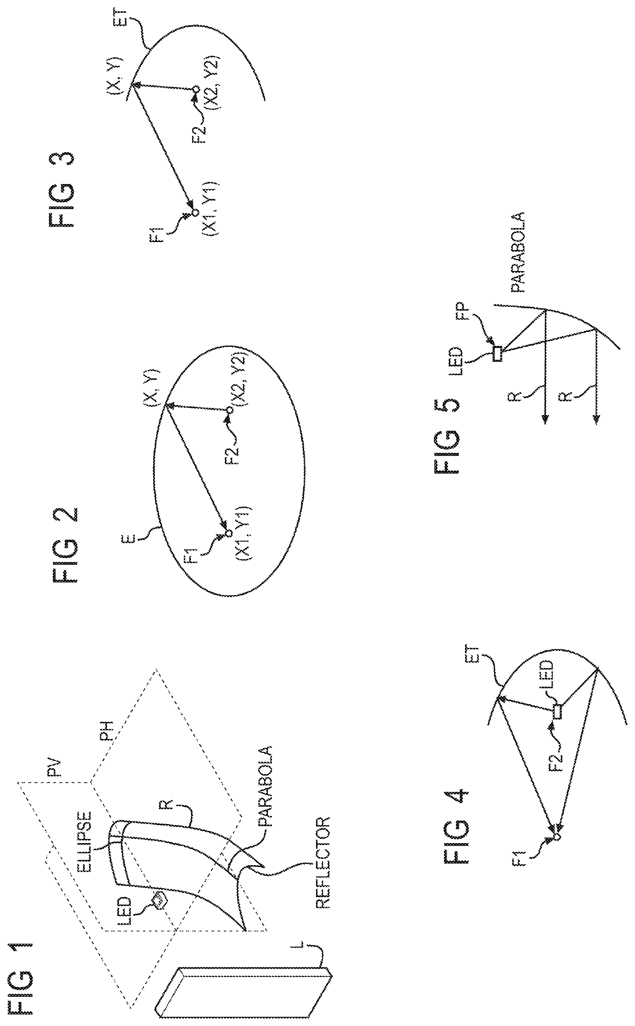
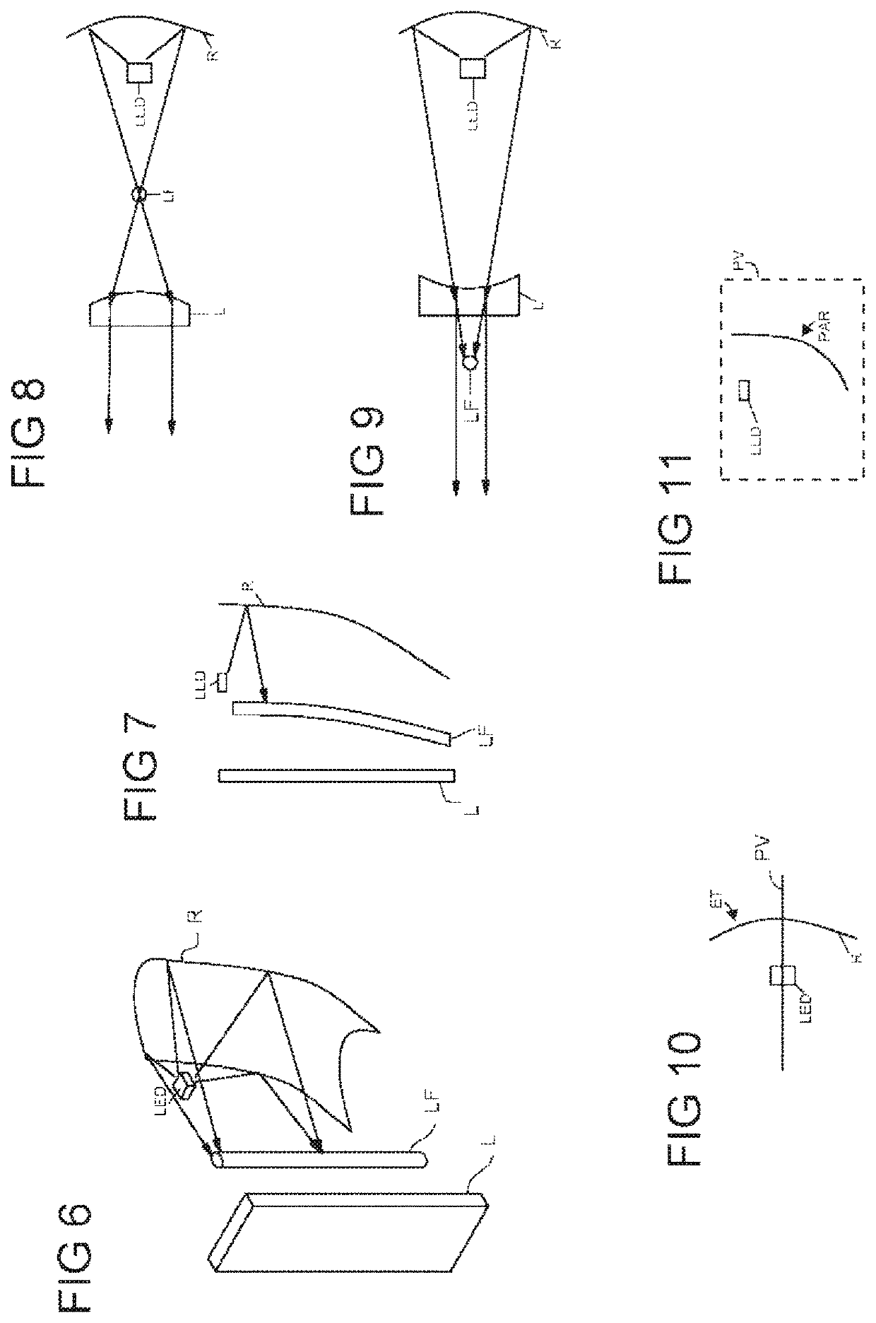
[0141]The invention concerns a “thin aspect” headlight or other lighting and / or signaling devices, hereinafter collectively referred to as a lighting device, for vehicles. The “aspect” in “thin aspect” refers to “aspect ratio,” which is the ratio of height H to width W, or H / W. Thus, a thin aspect ratio refers to a headlight which is tall and narrow. However, despite the fact that the thin aspect light is tall and narrow, the lighting device provides a beam pattern that conforms to SAE and / or ECE standards. The beam is typically short and wide. That is, a thin aspect lighting device, which is tall and nar...


PUM


Abstract

A thin aspect lighting system and method are shown. The system and method include at least one module having a reflector that is generally elliptical in one cross-section and generally parabolic in another cross-section. Each module is adapted to generate at least one of a flat beam pattern, a high beam pattern or a low beam pattern, such as a low beam pattern with a kink or elbow. Also shown is a headlamp assembly having a plurality of modules that generate the same or a different light beam pattern. Manipulation and variation of facets and / or positions of various components, such as at least one light source, have been found to provide improved characteristics in one or more of the light beam patterns.

Description

CROSS-REFERENCE TO RELATED APPLICATIONS[0001]This application is a continuation of U.S. application Ser. No. 15 / 316,738, filed on Dec. 6, 2016, which is a U.S. National Phase application of PCT Application No. PCT / US2015 / 034439 filed Jun. 5, 2015, which claims priority to provisional U.S. Application Ser. No. 62 / 009,324 filed Jun. 8, 2014, to which Applicant claims the benefit of the earlier filing date. These applications are incorporated herein by reference and made a part hereof.BACKGROUND OF THE INVENTION1. Field of the Invention[0002]This invention relates to lighting systems, and more particularly, to a thin aspect forward lighting system with cutoff.2. Description of the Related Art[0003]At present, there are two large families of headlights. A first family, those of headlights herein called “of the parabolic type”, comprises headlights whose beam is mainly generated by a source of small dimensions mounted in a mirror which projects the rays onto the road in order to form the...

Claims


Application Information

Patent Timeline
Patent Type & Authority Applications(United States)
IPC IPC(8): F21S41/147F21S41/32F21S41/33F21S41/26F21S41/148F21S41/153F21S41/141F21S41/36F21S41/657B60Q1/04
CPCF21S41/148F21S41/337F21S41/26F21S41/657F21S41/323F21S41/153F21S41/141F21Y2115/10F21S41/336F21S41/36F21S41/147B60Q1/04F21V13/04
Inventor POTTER, BRANTORISICH, JOHNBERRY, MATTHEW
Owner VALEO NORTH AMERICA
Learn More